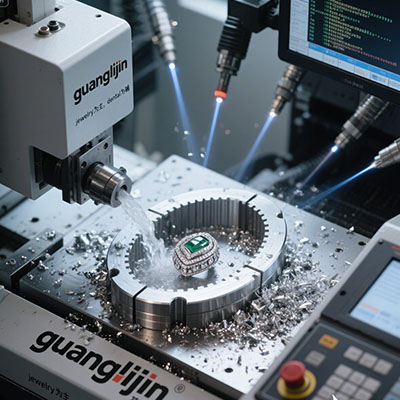
Aerospace components expose a five-axis mill faster than any other work. Deep pockets, thin walls, compound angles, and tight true position all converge on one part. The machine either holds or it does not. This guide explains what a cnc 5 axis mill must deliver for aerospace component machining, which specifications predict success, and how to validate a platform before committing capital.
Why Aerospace Components Stress a Five-Axis Mill
Aerospace geometry rarely stays simple. A single housing may combine angled bosses, curved surfaces, and thin ribs. Each feature pushes the machine in a different direction. The tool must tilt and rotate while cutting, not between cuts.
That continuous motion demands more from the control. Tool-center-point management must hold the tip on path. The rotary axes must resist cutting force. The frame must damp vibration as the head swings. Weakness in any link shows up as chatter or drift.
Therefore the purchase decision should center on dynamic capability. Static positioning accuracy at rest says little about behavior under load. Buyers who evaluate only static numbers often discover the gap on the first complex part.
Our team reviewed an aerospace component program in 2025 where a mill held tolerance on aluminum brackets. On a thin-wall titanium housing, the surface rippled at full tilt. The rotary axis lacked stiffness. The spec sheet never mentioned it.
Project A vs Project B: Aerospace Five-Axis Comparison
Two aerospace suppliers bought five-axis mills for component work. Project A chose a compact trunnion platform. Project B selected a larger gantry machine with a swivel head. Their part mixes differed, and so did their results.
| Factor | Project A — Compact Trunnion | Project B — Gantry Swivel Head |
|---|---|---|
| Part size | Small to medium components | Large structural parts |
| Rotary stiffness | Excellent at small envelope | Depends on gantry build |
| Thermal mass | Lower, faster warm-up | Higher, slower warm-up |
| Accessibility | Good for detailed multi-face work | Strong for long parts |
| Typical accuracy risk | Rotary wear over time | Gantry deflection at extension |
| Best fit | Precision housings, brackets | Large frames with moderate tolerances |
Project A held tight tolerance on compact aerospace housings. Project B handled long structural sections without repositioning. However, Project B needed a stiffer gantry to avoid chatter at full extension. The comparison forces a practical question: what does your contract part envelope actually look like?
Five Steps to Validate a Five-Axis Mill for Aerospace Components
Do not accept a demo on aluminum scrap. Do not trust a calibration certificate alone. Run this sequence with your alloy and your tightest feature.
Step 1: Demand a Simultaneous Five-Axis Cut on Your Alloy
Provide a test file with a compound angle and a thin-wall section. Watch the tool tip on the control display. It should track without hesitation. Listen for spindle load spikes at direction changes. Titanium and stainless expose weakness that aluminum hides. Measure true position and finish afterward .
Step 2: Verify RTCP Under Continuous Motion
Ask for a test that tilts the head through a continuous arc while cutting. Without RTCP, the tool tip drifts and the feature fails. Request sample G-code. Look for simultaneous rotary and linear commands. Indexed output disguised as multi-axis will not hold aerospace surfaces .
Step 3: Measure Rotary Stiffness and Backlash
Approach a feature from both directions and measure the difference. That is backlash. Then repeat the same move twenty times and measure spread. Small backlash can be compensated. Poor repeatability cannot. Aerospace true-position callouts depend on repeatability, not just accuracy.
Step 4: Test Thermal Stability Over a Long Cycle
Run the machine at production load for four hours. Measure the same feature at the start and the end. Aluminum expands about 23 microns per meter per degree Celsius . A drifting machine reveals itself over time. Confirm the warm-up routine and thermal compensation before first article.
Step 5: Audit the CAM Post, Probing, and Workholding
Ask the vendor to post your test geometry through their recommended CAM output. Inspect the code for continuous motion. Then review probing. In-process verification catches drift before scrap. Plan workholding for the actual cutting angles. A fixture that held a flat part may slip on a tilted surface.
Common Mistakes in Aerospace Five-Axis Machining
⚠Attention: Do not buy for your average part. Buy for your hardest part and your tightest tolerance. A machine that passes a soft-material demo may struggle on your production alloy.
⚠Attention: Do not ignore the post-processor. A machine labeled five-axis still produces three-axis output if the CAM post cannot handle simultaneous motion. Test the post with your geometry before purchase .
⚠Attention: Never skip warm-up on tight-tolerance work. A cold machine changes size as it heats. Run the full motion range before first article. Probe critical features on a fixed schedule .
Another quiet error involves fixture stiffness. Five-axis cutting changes force direction constantly. A fixture that held a flat part may flex on a tilted cut. Plan workholding for the actual cutting angles, not just the flat profile.
Frequently Asked Questions
What should I look for in a CNC 5 axis mill for aerospace components?
Check rotary stiffness, RTCP capability, thermal control, and CAM post compatibility. Request a live cut on your alloy. A machine that holds tolerance through a full shift is the one worth buying .
What tolerance can a 5 axis mill hold for aerospace parts?
Precision five-axis mills can hold ±0.001 inch or tighter under controlled conditions. Achievable results depend on thermal control, rotary repeatability, and probing discipline. Request a test cut on your alloy .
Why is RTCP critical for aerospace five-axis machining?
RTCP keeps the tool tip on its programmed path while the rotary axes move. Without it, compound-angle features and free-form surfaces drift. Aerospace parts rarely tolerate that drift .
How much does a CNC 5 axis mill cost for aerospace components?
Entry-level five-axis platforms start around $120,000–$200,000. Aerospace-class machines with high-rigidity rotary axes and thermal compensation run $250,000–$500,000 or more. Price tracks envelope, spindle power, and control quality.
Can a 5 axis mill cut titanium and Inconel aerospace parts?
Yes, with sufficient spindle torque, rigid construction, and through-spindle coolant. Light machines chatter and burn tools in these alloys. Confirm the torque curve and coolant strategy before purchase .
Pre-Purchase Checklist
- ☐ Contract part envelope and alloy mix documented
- ☐ Tightest tolerance and feature alignment requirement defined
- ☐ Simultaneous five-axis cut observed on your alloy
- ☐ RTCP verified under continuous motion
- ☐ Rotary backlash measured from both directions
- ☐ Rotary repeatability tested over twenty cycles
- ☐ Thermal stability measured over a four-hour run
- ☐ Spindle torque curve matched to alloy mix
- ☐ CAM post verified for simultaneous output
- ☐ Probing schedule and in-process verification planned
- ☐ Workholding plan sketched for tilted cutting angles
- ☐ Service access and spare rotary parts lead time confirmed
A five-axis mill for aerospace components is a system purchase: frame, control, CAM, and process discipline working together. Start with your hardest geometry, survive a live cut test, and end with a checklist on the floor. Everything else is brochure noise.