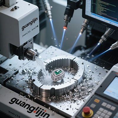
3 axis CNC programming turns a part plan into controlled machine motion. A safe, useful program depends on more than the visible cutting path. It needs the correct units, work reference, tool data, clearances, and machine-specific output. Start with a verified setup plan and treat program proving as part of the job, not an optional final check.
Connect the Drawing to the Setup
Identify the surfaces to cut and the stock that remains before each operation. Define the work reference and how the blank is held. Then select tools with enough reach and clearance. If those choices change, update the CAM setup and review the affected operations rather than assuming the old program remains valid.
Keep program revisions tied to tool and fixture records. An operator needs to know which file was approved and which physical setup it describes. A familiar filename can hide an old offset assumption or a different tool length. Use a clear release method so edits do not reach the machine without review.
Two Reference Details That Matter
Haas identifies G54 through G59 as work coordinate systems one through six. [Source 1: Haas Automation, G54–G59 Work Coordinate System reference.] These codes select references; they do not prove those references were measured correctly. Confirm the intended offset and the actual setup before interpreting the programmed positions.
The Haas programming workbook describes G154 P1 through P99 as additional work offsets for supported controls. [Source 2: Haas Automation, Mill Programming Workbook, Work Coordinate Selection.] This is controller-specific information. Check the exact machine and software support before using an offset scheme copied from a different installation.
Project A vs Project B: Manual Code or CAM Output
Simple features may suit a carefully reviewed manual program. Complex surfaces often benefit from CAM. Both routes still need verification against the physical machine. CAM can generate a plausible path from incorrect setup data, while hand-written code can contain reference or modal mistakes. Choose the method your team can validate reliably.
| Decision | Project A: Manual program | Project B: CAM program |
|---|---|---|
| Useful starting task | Simple understood geometry | More involved tool paths |
| Main review | Code logic and setup assumptions | Setup model and post output |
| Final requirement | Controlled machine proving | Controlled machine proving |
A Five-Step Programming Workflow
- Define the setup. Record stock, fixture, work reference, and drawing revision.
- Select tools. Confirm geometry, reach, holders, and required offsets.
- Create the operations. Review cutting order, remaining stock, and safe transitions.
- Validate the output. Use the approved post and check the complete program against the machine configuration.
- Prove and inspect. Follow the shop’s controlled first-run procedure and measure the sample.
An Illustrative Offset Error
Imagine a program written for one vise position but loaded with another work offset active. The tool path may be correct in its intended coordinate system while the physical result is wrong. The fix begins with reference control. Recalculating the tool path will not help if the operator still selects an unintended offset.
While researching this guide, I compared the basic and extended work-offset references. The documents made the importance of controller context clear. I would record the approved offset scheme with the program release, rather than expecting operators to infer it from a generic sample or a file written for another machine.
⚠ Attention: Never run unverified code merely because it uses familiar axis letters. Units, offsets, tool data, and supported commands can differ. Keep fixtures and rapid moves in the review. Use the machine maker’s proving procedure and trained supervision before allowing a new program to cut valuable work.
Programming Questions
Does CAM remove the need to understand code?
No. The operator and programmer still need to understand the setup and validate the output. CAM relies on the supplied model, tool data, and post configuration. Learn how the control interprets the relevant commands and references. That knowledge helps identify problems before the first physical move becomes a collision or scrap part.
Can one program run on different mills?
Only after confirming compatibility and the complete setup. Controls, travel, tool handling, and supported commands may differ. Use the correct post or an approved conversion process and validate the result. Do not treat a shared three-axis layout as permission to transfer a production file unchanged between machines.
What should programming support include?
For 3 axis CNC programming, request setup sheets, tool lists, post details, file revisions, and proving support. Define who approves the first part and who maintains later changes. A useful service delivers a repeatable process and records, not only a code file with undocumented assumptions.
Checklist
- Stock and fixture match the setup model.
- Units and work offsets are confirmed.
- Tools and holders match the records.
- Rapid and linking moves are reviewed.
- The post matches the control.
- The first part and released file are approved.