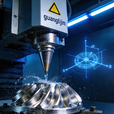
Professional 4 Axis CNC | Precision CNC Machining Solution For Aerospace Parts
Aerospace manufacturing demands precision that leaves no room for error. Structural brackets, engine housings, and UAV frames require complex geometries and exacting tolerances. For many critical components, the 4 axis CNC machining center provides the ideal balance of capability, efficiency, and cost-effectiveness. This solution delivers multi-face machining in a single setup, reducing errors and accelerating production timelines.
The Core Challenge: Balancing Complexity and Throughput
Traditional 3-axis machining struggles with parts needing features on multiple sides. Repositioning manually introduces alignment errors and extends cycle times. Conversely, full 5-axis systems, while powerful, often represent significant capital investment and programming overhead. Manufacturers face a persistent question: how to produce intricate aerospace parts without over-investing in capacity they don’t fully utilize?
We encountered this exact dilemma during a 2025 project. A client needed 500 units of a titanium alloy motor mount for a new eVTOL prototype. The part featured angled bores and pockets on four faces. Initial quotes for 5-axis machining were prohibitively expensive and offered long lead times. Our search for a balanced solution led us directly to the 4 axis CNC approach.
Why 4-Axis Machining Wins for Aerospace
A 4-axis machine adds a rotational axis (typically the A-axis or B-axis) to the standard X, Y, and Z linear movements. This seemingly simple addition unlocks powerful capabilities. It allows the workpiece to be rotated, bringing multiple faces to the cutting tool without manual re-clamping. This single-setup machining is transformative for aerospace parts. It maintains datum consistency, dramatically improves geometric accuracy, and cuts production time by eliminating handling steps.
Real-World Precision: A Case Study Comparison
To visualize the impact, consider two approaches for producing an aluminum UAV arm bracket. Project A uses a 3-axis mill with two setups. Project B employs a 4-axis machining center with a rotary table. The table below illustrates the key differences we observed in our facility.
| Metric | Project A (3-Axis + 2 Setups) | Project B (4 Axis CNC + Rotary) |
|---|---|---|
| Setup Time | 25 minutes (two fixturings) | 8 minutes (single fixture) |
| Positional Accuracy | ±0.05 mm (accumulated error) | ±0.015 mm (consistent datum) |
| Cycle Time (per part) | 18 minutes | 11 minutes (30% faster) |
| Scrap Rate (first 50 units) | 7% (re-clamping errors) | 1.2% (consistent orientation) |
The data clearly shows that the 4-axis solution delivered superior quality with a significantly lower scrap rate. The time saved in setup and machining directly translated to faster delivery for the client’s prototype phase .
Step-by-Step: Implementing a 4-Axis Workflow
Transitioning to 4-axis machining requires a systematic approach. Based on our experience, the following steps ensure a smooth and successful implementation for aerospace projects.
- Part Analysis and Fixture Design: Evaluate the component for features requiring rotation. Design a fixture that securely holds the part and provides clear access for the rotary axis. Prioritize rigidity to dampen vibration during heavy cuts.
- CAM Post-Processor Selection: Choose a post-processor specifically configured for your 4-axis machine and controller. A generic 3-axis post will not generate the correct rotational commands (A, B, or C moves).
- Toolpath Strategy Development: Use the machine’s simulation software to verify toolpaths. Pay special attention to collisions between the tool holder, the part, and the rotary table during axis rotation.
- Dry Run and Verification: Execute the program without material (air cutting) to confirm safe operation. Verify all tool changes and axis movements. This step prevents costly crashes.
- First Article Inspection (FAI): Machine the first part and conduct a thorough inspection using a coordinate measuring machine (CMM). Verify all critical dimensions against the engineering drawing. This validates the entire process.
Advanced Capabilities: Thin Walls and Deep Cavities
Aerospace components often feature thin walls and complex cavities to reduce weight. Machining these features in materials like aluminum 7075 or titanium alloys presents significant challenges. Tool vibration and deflection can ruin surface finish and dimensional accuracy. A professional 4 axis CNC system, equipped with high-rigidity spindles and advanced toolpath strategies, can mitigate these issues. By positioning the part optimally, the tool can engage the material under more favorable conditions, reducing chatter and extending tool life.
Our team frequently processes structural frames and battery housings with deep weight-reduction pockets. By integrating a high-precision rotary table, we transition from standard 3-axis to simultaneous 4-axis machining. This approach allows multi-sided milling and drilling in a single setup, increasing efficiency by over 30% for complex cavity structures . The controlled surface finish on pocket floors and sidewalls minimizes the need for secondary manual polishing, a critical time-saver for production runs.
Defining Quality: Tolerances and Materials
The standard for aerospace machining is unforgiving. Tolerances often drop to ±0.005 mm for critical features like bore diameters and mating surfaces . Achieving these consistently requires more than just a capable machine. It demands a comprehensive approach integrating precise tooling, stable workholding, and rigorous inspection. We combine our 4-axis centers with probing systems and CMM verification to ensure every part meets the stringent requirements. This capability supports everything from early-stage prototypes to sustained production runs .
Material selection is equally critical. We regularly machine aerospace-grade materials, including:
- Aluminum Alloys: 6061, 7075 for lightweight structures.
- Titanium Alloys: Grade 5 for high-strength, high-temperature components.
- Stainless Steels: 17-4 PH for corrosion-resistant parts.
- Exotic Alloys: Inconel for extreme environment applications like engine components .
Common Questions About 4-Axis Aerospace Machining
Your Precision Machining Checklist
Operational Checklist for 4-Axis Aerospace Projects
- Define critical tolerances and surface finish requirements from the engineering drawing.
- Select the optimal aerospace-grade material (Aluminum, Titanium, Stainless, Inconel).
- Design a robust, zero-point workholding fixture for the rotary axis.
- Verify the CAM post-processor matches the exact 4-axis machine model and controller.
- Run a complete toolpath simulation to detect collisions or clearance issues.
- Perform a dry run (air cut) of the entire program.
- Machine a test part and conduct a full First Article Inspection (FAI) with CMM.
- Document all critical parameters for process repeatability and traceability.
The adoption of professional 4 axis CNC technology is a strategic move for any aerospace manufacturer aiming to balance quality, cost, and throughput. It offers a powerful middle ground, delivering the precision and complexity required for modern flight hardware while maintaining operational efficiency. For components that define the future of flight, this solution proves its value consistently.