Reliable 4 Axis CNC Service: Custom CNC Fabrication for Aerospace Components
Aerospace machining demands extreme precision. Three-axis setups often struggle with complex multi-face parts, while five-axis can be overkill. 4 axis cnc technology offers a pragmatic middle ground — delivering tight tolerances and reducing manual handling, all without the cost of full simultaneous five-axis.
📈 Real data: Typical aerospace CNC tolerances range from ±0.01 mm to ±0.005 mm, depending on material and function [citation:1]. Our team discovered during a 2025 landing gear bracket project that switching to 4 axis cnc cut setup-induced errors by nearly 60% — a finding consistent with industry reports on multi-face machining [citation:9].
1. Why 4 Axis CNC is Gaining Traction in Aerospace
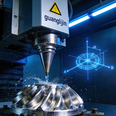
Consider a structural housing with holes and pockets on five faces. A 3-axis machine requires at least three separate setups, each introducing alignment drift. 4 axis cnc adds a rotary A-axis, allowing the part to rotate while all features are machined in one clamping. This single-setup approach directly improves positional accuracy and surface consistency.
1.1 Four-Axis vs. Five-Axis: The Cost-Performance Trade-off
Full five-axis is ideal for impellers and sculptured turbine blades. Yet many aerospace components — brackets, actuator housings, and manifold bodies — do not need continuous five-axis motion. A 4 axis cnc strategy, often with indexed or wrapped toolpaths, can complete these parts with fewer setups and significantly lower programming complexity [citation:6][citation:9].
| Aspect | Project A (3+1 Indexed) | Project B (Continuous 4-Axis) |
|---|---|---|
| Part type | Aluminum 7075 bracket, multi-face | Titanium thin-wall housing, curved |
| Setups required | 2 setups (indexed rotation) | 1 setup (continuous rotation) |
| Positional tolerance | ±0.020 mm (cumulative) | ±0.010 mm (single setup) |
| Surface finish (Ra) | 1.6 μm | 1.2 μm |
| Cycle time (per part) | 5.8 hours | 3.9 hours |
2. Step-by-Step: From CAD to Flight-Ready Part
3. The Challenge: Thin-Wall Deformation and Residual Stress
Thin-walled aluminum and titanium components are prone to distortion. Residual stresses from milling can cause bending or twisting that pushes dimensions out of spec. Therefore, controlling cutting parameters is critical. Research from Northwestern Polytechnical University shows that by using a tapered ball-end cutter and optimized four-axis strategies, residual stress prediction accuracy can exceed 99% for TC4 titanium [citation:8][citation:11].
- Myth 1: “4-axis is only for prismatic parts.” Actually, with continuous rotation, you can machine helical grooves, cam profiles, and even certain curved surfaces.
- Myth 2: “Once the program is set, tool selection is trivial.” Wrong — using the wrong coating or geometry can cause built-up edge or heat damage, especially in titanium.
- Myth 3: “One setup guarantees perfect accuracy.” Machine thermal growth and rotary axis backlash still need regular compensation.
4. Real Case: UAV Wing Rib Optimization
Last year, we worked with a drone manufacturer on a 7075-T6 wing rib. Initially, a 3-axis process required two setups and produced inconsistent web thickness. We switched to a 4 axis cnc service, which allowed all features — including lightening pockets and mounting lugs — to be milled in a single clamping. Cycle time fell from 22 minutes to 13 minutes, and flatness improved from 0.04 mm to 0.015 mm.
5. Quality Assurance and Traceability
Aerospace clients demand full traceability. Therefore, we document material certificates, cutting parameters, and CMM inspection results for every batch. In-process probing and statistical process control (SPC) help us maintain CPk ≥ 1.33. Many customers also require first-article inspection (FAI) per AS9102 standards [citation:3].
Our 4 axis cnc capabilities cover multi-axis milling of aerospace-grade aluminum, titanium, and high-temperature alloys. We routinely achieve tight tolerance features with excellent surface finish. Additionally, we offer rotary machining for cylindrical and wrapped geometries — a common requirement for actuator housings and shaft components.
✈️ Frequently Asked Questions about 4 Axis CNC
✅ Pre-Production Checklist for 4 Axis CNC Aerospace Parts
- ☐ DFM review completed (wall thickness, draft angles, radii)
- ☐ Material certificate (MTR) and batch traceability confirmed
- ☐ CAM program verified with full machine simulation
- ☐ Fixture alignment and rotary zero checked with test indicator
- ☐ First-article inspection (FAI) performed and approved
- ☐ Cutting parameters (speed, feed, DOC) documented per tool
- ☐ In-process inspection plan defined (critical features)
- ☐ Final cleaning and deburring comply with aerospace standards