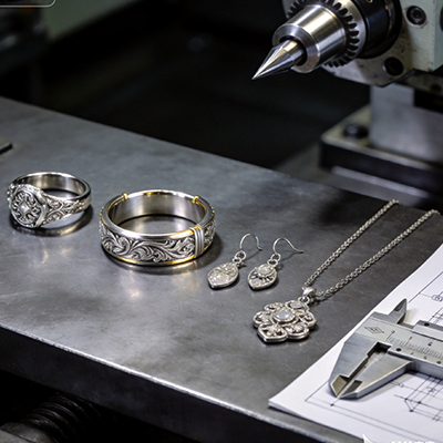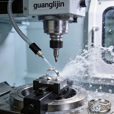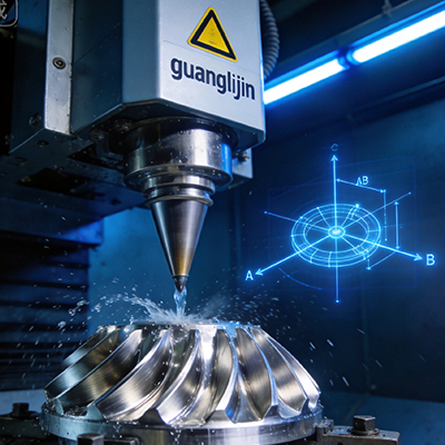
5 axis CNC workholding must leave room for the cutter while resisting the forces of machining. A low clamp can improve access, but a weak hold can ruin the part. The right buying decision balances support, clearance, and repeat loading. For jewelry and small components, test the fixture on the thinnest and most awkward part you expect to make.
Define What the Fixture Must Protect
Begin with the surfaces that must remain free of marks. Identify where the stock is strong enough to grip and where the tool needs access. A ring blank may allow a temporary holding section. A finished pendant may not. Write these limits on the drawing so fixture choices do not quietly change the product.
Keep the center of the work close to a stable support where practical. Raising it may improve access but can increase leverage on the hold. Check the full moving assembly, including jaws, mounting plates, and fasteners. A small part can still create a large collision envelope when the table tilts.
Read Capacity Figures in Context
Haas describes its large five-axis gantry machines as using a two-axis spindle head for angular access. [Source 1: Haas Automation, 5-Axis Machines, Large-Scale 5-Axis Mills.] A head-tilting layout has different clearance concerns from a tilting table. Ask which components move around your fixture rather than relying on the shared axis count.
Roland DGA lists maximum material thickness of 40 mm for the DE-3, falling to 38 mm with its nose cone. [Source 2: Roland DGA, DE-3 specifications.] These are model-specific engraving limits. They illustrate why installed accessories matter. Confirm fixture clearance on the actual machine, with the tool and accessories fitted.
Project A vs Project B: Standard Jaws or Custom Support
Standard jaws can be quick to source and easy to replace. Custom jaws can support a delicate shape or keep clamps away from a critical face. Neither choice is automatically more precise. Check how the part locates, how force reaches the support, and how an operator can tell that the work is fully seated.
| Decision | Project A: Standard jaws | Project B: Custom nest |
|---|---|---|
| Best starting point | Simple, firm stock | Shaped or thin work |
| Main check | Grip and accessible faces | Fit, support, and chip traps |
| Repeat loading | Defined stops and clean jaws | Defined locating faces and seating check |
Prove the Fixture in Five Steps
- Mark locating faces. Separate the surfaces that locate the part from those that apply force.
- Model the whole assembly. Include jaws, bolts, base plates, and the stock in clearance checks.
- Test seating. Load and unload a blank. Check that chips or burrs cannot create a false seat.
- Run a controlled cut. Use approved clamp forces and machining conditions. Stop if the work shifts.
- Measure after release. Compare loaded and free-state results where part flex may matter. Repeat on another blank.
An Illustrative Thin-Ring Trial
Imagine a thin ring blank that looks round while clamped but changes shape when released. The first question is whether the jaws distort it. A longer supported contact area may help, but excessive force can still cause trouble. The trial should compare the free part with the drawing, not just the held part.
During preparation of this guide, I reviewed the difference between moving-head access and accessory-dependent clearance. That research highlighted a gap in many simple fixture descriptions: they show the part without the rest of the moving assembly. For a useful supplier review, keep both the complete fixture and machine motion visible.
⚠ Attention: More clamp force is not a universal cure for movement. It can distort thin stock or damage finished surfaces. Follow the fixture maker’s limits. Never remove guards or improvise unsupported extensions to gain access. If a safe grip blocks the cut, change the process plan or fixture design.
Questions for Fixture Suppliers
Should every small part use custom jaws?
No. Simple stock may work well in a standard system with clear locating stops. Custom jaws make sense when they solve support, access, or surface protection issues. Ask for the same repeat-loading trial with either option. A custom shape alone does not prove that an operator will seat the part consistently.
How do you compare fixture repeatability?
Remove, clean, and reload the part using a written method. Measure the features that matter to the job from consistent references. Record both the procedure and the results. Do not confuse a maker’s fixture rating with total part accuracy, which also depends on the blank, machine, tooling, and cutting process.
What should a workholding quote contain?
For 5 axis CNC workholding, specify part material, blank shape, accessible faces, and finish limits. Include base interfaces, jaws, fasteners, setup instructions, and replacement parts. Request a clearance review and proof cut. The useful deliverable is a repeatable loading and cutting method, supported by the correct hardware.
Checklist
- Locating faces and clamping surfaces are clear.
- Thin walls remain supported.
- All moving clearances are checked.
- Chip traps can be cleaned.
- Free-state dimensions pass inspection.
- Reloading gives consistent results.