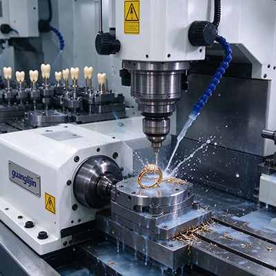
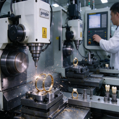
The Z axis is the most heavily loaded linear assembly on a vertical machine. It carries the spindle, absorbs cutting thrust, and fights gravity all day. Sourcing and machining that axis demands a different playbook than the X and Y axes. This guide covers supply strategy, machining practice, and integration checks.
The Supply Chain Problem: Who Actually Builds a Good Z Axis?
Buyers often treat the cnc machine z axis as a commodity subassembly. That view costs money. A poorly sourced Z column shows up as chatter at the tool tip six months after commissioning. The supplier list matters as much as the drawing.
Three supply models dominate the market. Full assembly suppliers ship a complete column with guideways, ballscrew, and bearing blocks pre-aligned. Component suppliers ship individual parts. Integrators buy components and assemble in-house. Each model carries a different risk profile.
Full assembly suppliers reduce your machining burden. They also lock you into their tolerances. Component supply gives flexibility but pushes alignment work onto your floor. Integrators sit in the middle. They buy the screw from one vendor, the guideways from another, and own the final geometry.
Supply lead time varies widely. A precision-ground ballscrew for a Z axis typically runs 6–10 weeks from order. Linear guide rails run 4–8 weeks. Full column assemblies can stretch to 14 weeks. Plan the Z axis order before the frame order. The column arrives last and blocks the build.
Machining the Z Axis Column: Tolerance Stack Reality
The column casting must hold flatness and perpendicularity across long surfaces. A vertical machining center column for a 1-meter Z stroke needs the guide mounting faces square to the spindle axis within 10–15 µm over the full length. Thermal distortion during machining of the casting itself can blow that budget.
Rough machine the casting first. Let it relax for 48 hours. Then finish machine. This two-stage sequence releases residual stress before the final cuts. Skipping the relaxation step produces a column that moves after installation.
Ballscrew bearing housings are the second critical feature. The angular contact bearing pair needs a bore tolerance of H6 or better. Bearing seat shoulder squareness must stay under 5 µm. A tilted bearing seat pushes the screw into a bending load. That load shows up as uneven wear on the nut.
Guide rail mounting surfaces need consistent surface finish. Too rough and the rail rocks. Too smooth and the rail slides during tightening. Aim for Ra 1.6 µm on the rail mounting face. Use a torque pattern for rail bolts — center outward, two passes.
Comparing Two Sourcing Strategies: Project A vs. Project B
| Parameter | Project A: Full Assembly Supply | Project B: In-House Integration |
|---|---|---|
| Lead time | 12–14 weeks | 8–10 weeks (components in stock) |
| Alignment responsibility | Supplier | Your machining floor |
| Unit cost | Higher — supplier margin plus alignment labor | Lower — labor absorbed internally |
| Quality risk | Single point of accountability | Split across multiple vendors |
| Flexibility | Low — fixed configuration | High — mix guideway and screw brands |
| Best fit | Low-volume machine builders | High-volume builders with metrology capability |
Project A built twelve vertical machines with assembled columns. The supplier held perpendicularity to 8 µm. Project B built the same machine from components. Their first three columns showed 18 µm perpendicularity. Rework cost ate the component savings. By column nine, Project B had dialed in the process and matched Project A’s geometry at lower cost.
Ballscrew Machining and Preload: Where Accuracy Lives
The Z axis ballscrew takes axial load in both directions. A double-nut preloaded screw handles that load without play. Single-nut screws with oversized balls work for lighter duty. For a spindle-carrying Z axis, double-nut is the safer spec.
End machining of the screw needs a lathe with a traveling steady. The journal diameters for the bearing seats require grinding, not turning. Turning leaves tool marks that create vibration under preload. Grind to IT5 and hold concentricity between the two end journals under 5 µm.
Preload value selection matters. Too little preload and the nut rattles during Z retract. Too much preload and the screw runs hot. For a 40 mm diameter screw on a vertical axis, a preload of 3–5% of dynamic capacity is a common starting point. Verify by measuring screw temperature after a 30-minute rapid traverse cycle.
Step-by-Step: Z Axis Ballscrew Installation
- Clean the bearing bores. Remove all chips and preservative oil. Wipe with lint-free cloth and solvent.
- Press the angular contact bearing pair. Orient the pair face-to-face or back-to-back per the drawing. Heat the housing if the fit is tight.
- Insert the screw from the motor end. Slide gently through the nut. Never let the screw’s own weight hang on the nut unsupported.
- Set bearing preload. Tighten the locknut to the specified torque. Check axial play with a dial indicator — target under 2 µm.
- Align the nut bracket. Loosen the bracket bolts. Jog the Z axis through its full stroke. Tighten bracket bolts at mid-stroke.
- Run a break-in cycle. Traverse full stroke at 50% rapid for 30 minutes. Re-check backlash and screw temperature.
Field Integration: Lessons from the Floor
Our team integrated a batch of Z axis columns in 2025 for a drilling center program. The columns arrived with guideways mounted but ballscrews separate. We found that two of eight columns had guide rail straightness outside the 8 µm spec — a supplier inspection gap. We caught it during laser alignment before assembly, not after.
The lesson is simple. Incoming inspection on a Z axis column must include guide rail straightness and mounting face flatness. Do not trust the supplier’s certificate alone. A 30-minute laser check saves a week of rework.
Counterbalance setup is another field issue. Pneumatic counterbalance cylinders need pressure set to match the spindle head weight. Under-pressure causes the motor to fight gravity on the way up and overshoot on the way down. Over-pressure lifts the head when the brake releases. Set pressure with a gauge, then verify by disabling the servo and watching for drift.
Servo coupling alignment closes the integration loop. Angular misalignment between motor and screw creates a once-per-rev torque ripple. That ripple shows up as surface finish variation on Z-interpolated moves. Use a dial indicator on the coupling hub. Target under 0.02 mm radial and 0.01 mm angular offset.
Frequently Asked Questions
What is the typical lead time for a custom CNC machine Z axis assembly?
Custom Z axis assemblies run 10–14 weeks depending on ballscrew grinding and guideway stock. Standard component supply runs 6–10 weeks. Order the Z axis early in the machine build schedule.
Should I buy a complete Z axis column or machine it in-house?
Buy complete if your volume is low and metrology capacity is limited. Machine in-house if volume justifies the alignment labor and you have laser alignment equipment on site.
How do I verify Z axis ballscrew preload after installation?
Measure axial play with a dial indicator at the spindle nose. Command small Z moves in both directions. Play above 3 µm means the preload is too light or the locknut has loosened.
What guideway type suits a high-speed CNC machine Z axis?
Linear guides suit high-speed Z axis positioning and rapid tool changes. Box ways suit heavy cutting and vibration damping. Hybrid machines combine both, using linear guides on X/Y and a box way on Z.
How do I check Z axis column perpendicularity during incoming inspection?
Use a granite square and a dial indicator on the guide mounting face. Measure deviation along the full stroke length. Also check the spindle bore axis relative to the guide face with a test bar.
Z Axis Machining & Supply Checklist
- Confirm lead time for ballscrew and guideway before releasing the frame order.
- Rough machine the column casting, relax 48 hours, then finish machine.
- Verify bearing seat bore tolerance to H6 and shoulder squareness under 5 µm.
- Grind ballscrew bearing journals — do not turn them.
- Inspect incoming guide rail straightness with a laser or dial indicator.
- Set ballscrew preload to 3–5% of dynamic capacity and log the value.
- Align the nut bracket at mid-stroke, not at the end of travel.
- Check coupling angular and radial misalignment before running the servo.
- Set counterbalance pressure with a gauge and verify head drift with the brake off.
- Ship the column with a screw support brace or the screw removed.