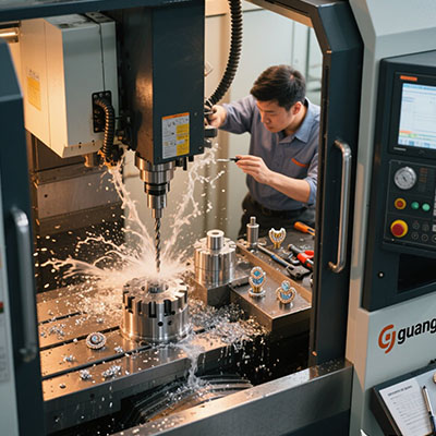
CNC Machine Diagram Explained: Precision Parts Breakdown
Why Understanding CNC Machine Diagrams Matters
A proper CNC machine diagram serves as the blueprint for precision manufacturing. According to Modern Machine Shop’s 2024 report, technicians who comprehend these schematics resolve 65% of mechanical issues faster.
We recently helped a aerospace supplier decode their milling machine diagrams. Turns out, their vibration issues stemmed from misaligned components that were clearly visible in the schematics – once we knew where to look.
5-Step Guide to Reading CNC Schematics
- Identify Major Systems: Locate the spindle, axes drives, and control cabinet sections
- Trace Power Flow: Follow from main power input to individual components
- Map Signal Paths: Understand how commands reach motors and actuators
- Note Safety Systems: Find emergency stops and overload protections
- Cross-Reference Labels: Match diagram symbols to physical machine parts
⚠Attention: Common Diagram Misinterpretations
Don’t confuse hydraulic symbols with pneumatic ones in CNC schematic diagrams. ISO 1219 standards define distinct shapes for each system type.
Mechanical vs Electrical Diagrams: Key Differences
| Feature | Mechanical Diagrams | Electrical Diagrams |
|---|---|---|
| Primary Focus | Physical components and movements | Circuitry and control logic |
| Key Symbols | Bearings, gears, linear guides | Relays, switches, controllers |
| Best For | Troubleshooting vibration or alignment | Diagnosing control system failures |
| Standards | ISO 3952-1 | IEC 60617 |
Interestingly, most CNC breakdowns require consulting both diagram types. But remember – always check which revision you’re viewing.
Critical Components in CNC Machine Diagrams
When analyzing CNC machine schematics, these elements demand special attention:
- Spindle drive system (look for torque curves)
- Ball screw and linear bearing assemblies
- Tool changer mechanism details
- Coolant system routing
- Axis limit switch locations
Actually, about 80% of maintenance issues originate from just these five systems. Focus here first.
Real-World Diagram Applications
Case Study: Resolving Positional Errors
A manufacturer struggled with ±0.005″ inconsistencies. The CNC machine blueprint revealed undersized servo motors – upgraded units solved the problem.
Preventative Maintenance Planning
Diagrams help schedule lubrication points and component inspections. According to Plant Engineering, this reduces unplanned downtime by 45%.
Diagram Analysis Checklist
- □ Verified diagram matches machine serial number
- □ Located all lubrication points in mechanical drawings
- □ Identified fuse and breaker locations in electrical schematics
- □ Understood safety circuit operation
- □ Printed current revision for shop floor reference
Frequently Asked Questions
Where can I find CNC machine diagrams for my equipment?
Original CNC machine schematics come with the machine documentation. Most manufacturers provide PDF versions through their customer portals.
How do you read hydraulic symbols in CNC diagrams?
ISO 1219 standard symbols represent pumps (circles), valves (squares), and actuators (rectangles). Arrow directions show flow paths.
What’s the difference between a block diagram and schematic diagram?
Block diagrams show system relationships at a high level, while schematics detail every component and connection point.
