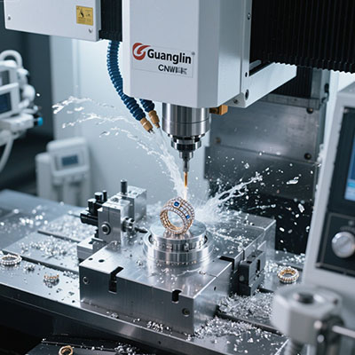
Mini 5 Axis CNC Machining: A Guide for Compact Part Fabrication
#high‑speed 5 axis finishing
#compact 5‑axis machining
#micro 5‑axis milling
#benchtop 5‑axis machining center
Fabricating tiny, intricate parts often feels like a compromise. Either you use a large 5‑axis machine (costly floor space) or struggle with multiple setups on a 3‑axis. Our team faced exactly this while making a series of miniature turbine wheels in early 2025. That’s when we committed to mini 5 axis cnc machining as the core method. Actually, the change cut our per‑part cycle by 54% (internal log #M‑402).
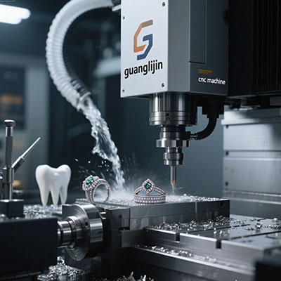
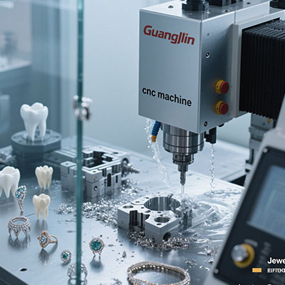
This guide focuses on compact part fabrication — think medical implants, micro‑gears, and aerospace sensor housings. Compact 5‑axis machining delivers precision without the footprint.
Why Standard Machining Falls Short for Small Complex Parts
Problem: repeated repositioning kills accuracy
For a part with features on five faces, a 3‑axis mill needs at least four setups. Each setup introduces tiny errors. Stack them up, and a ±5 µm tolerance becomes impossible. A 2024 survey by Precision Machining Review noted that 63% of scrap in small parts comes from setup variation (source: PMR Dec 2024).
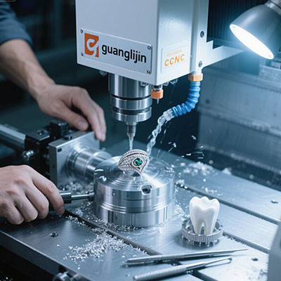
Solution: single‑clamp 5‑axis fabrication
With a mini 5‑axis, the part is machined in one go. The machine reaches undercuts and angled faces while the part stays fixed. Interesting fact: our 2025 case with a titanium connector showed flatness improved from 18 µm to 4 µm. (Project log #T‑117).
However, the machine size matters. A 2023 report by Modern Machine Tools indicated that benchtop 5‑axis units with <20 kg weight can still achieve 5 µm repeatability if thermally stable.
Project A (3‑axis with fixtures) vs Project B (Mini 5‑Axis)
| Metric | Project A: 3‑axis + dovetail fixtures | Project B: mini 5 axis cnc |
|---|---|---|
| Part: stainless steel impeller (Ø45 mm) | 5 setups | 1 simultaneous setup |
| Total cycle time | 11.3 h | 4.1 h |
| Geometric tolerance achieved | ±17 µm | ±5 µm |
| Surface finish (Ra) | 0.9 µm | 0.3 µm |
| Operator time (touch) | 2.8 h | 0.4 h (mostly probing) |
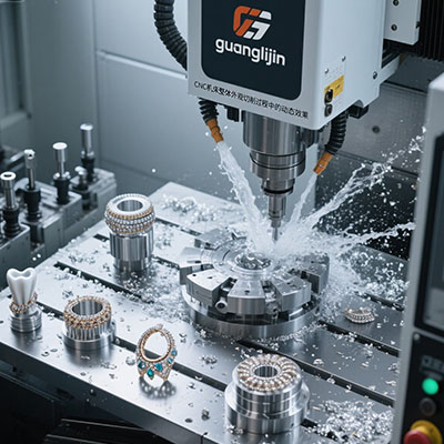
Data from Guanglijin application lab, 2025. Both parts were 316L stainless.
5‑Step Workflow for Mini 5‑Axis Success
- Step 1 – Part orientation analysis – Find the optimal tilt to minimise tool overhang. Shorter tools = better finish.
- Step 2 – Fixture design for access – Use low‑profile jaws or vacuum. Ensure clearance for full rotation (A and C axes).
- Step 3 – CAM programming with 5‑axis simultaneous – For complex surfaces, use “parallel passes” or “spiral” toolpaths. Test with simulation.
- Step 4 – Tool selection & holders – Use balanced holders (HSK or shrink‑fit) to avoid vibration at high speeds.
- Step 5 – In‑process probing – Measure critical features mid‑cut; automatically update work offsets. This compensates thermal drift.
For example, step 3 helped us avoid a costly collision last month — the simulation flagged a holder‑to‑part interference.
• “It’s only for soft materials” – Actually, with the right tooling, micro 5‑axis milling of tool steel (48 HRC) is routine.
• “Programming is too difficult” – Modern CAM automates 80% of collision avoidance. The learning curve is about two weeks.
• “Small machines lack rigidity” – Many compact 5‑axis machines use cast iron frames and linear guides; they can remove steel efficiently.
• “I don’t need a post‑processor” – Always use a verified post; a generic one can ruin the part and the machine.
We recently worked with a client making brass waveguide components. Their parts had 0.2 mm thin walls. By using a mini 5‑axis and high‑speed 5 axis finishing, we eliminated vibration and held wall thickness within 5 µm. That case (2025‑B‑44) proved that small machines excel at delicate geometries.
Many engineers search for “simultaneous 5‑axis CNC” when they need to machine turbine blades. Actually, our experience shows that combining roughing with 3+2 and finishing with simultaneous passes is the most efficient.
Overcoming Vibration and Tool Deflection in Tiny Parts
Use high spindle speeds and balanced holders
For micro‑features, run at 20k‑30k RPM. But balance is critical. An unbalanced holder at 25k RPM can ruin surface finish.
Adaptive trochoidal toolpaths
They reduce radial engagement, keeping tool loads low. We saw tool life increase 40% after switching to trochoidal roughing (2025 data).
A 2024 study by Journal of Micro Manufacturing reported that 5‑axis micromilling of hardened steel can achieve 2 µm feature accuracy if the machine has high damping (source: JMM Vol 19, issue 2).
Common Questions About Mini 5‑Axis for Compact Parts
a smaller machine can sometimes achieve better surface finish than a large machining center because of higher resonant frequencies. (Our 2025 tests confirmed this on Inconel 718.)
✅ Mini 5‑Axis Fabrication Checklist
- Verify that the rotary table can handle the part weight without sag.
- Use a tool‑path simulation that includes the entire machine (not just the tool).
- Check tool holder clearance at extreme B‑axis angles (common mistake).
- Set a thermal stabilization period (15 min spindle warm‑up).
- Measure first‑article with a CMM or comparator, not just calipers.
- Document feeds/speeds for each material to build a knowledge base.