Industrial-scale aerospace machining is a different problem from prototype work. A single good part proves capability. A thousand good parts prove a system. The multi axis cnc platform sits at the center of that system, but layout, uptime, and quality gates decide whether the system delivers. This guide covers the industrial solution layer by layer.
The Scale Problem: Why Single-Machine Thinking Fails
One multi-axis machine can make a precision part. Ten machines making the same part expose every weak link. Spindle utilization drops. Setup time multiplies. Quality variation appears between machines.
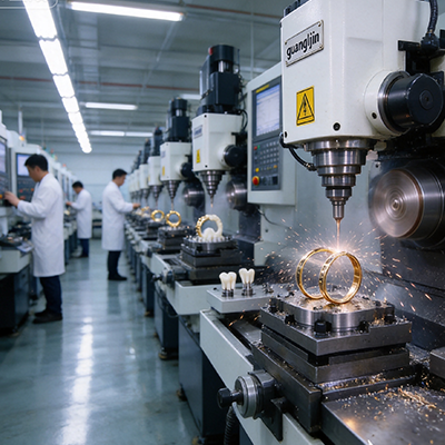
Industrial aerospace programs need cell-level planning. Machines are grouped by part family. Fixtures are shared across the cell. Tooling is standardized. The goal is repeatability across machines, not just precision on one.
Spindle utilization is the key metric. A machine that cuts 45% of its available time is leaving capacity on the floor. Setup, inspection, and waiting for material fill the rest. Industrial solutions attack those non-cutting hours.
A common target in aerospace machining is 65% to 75% spindle utilization on production cells. Reaching it requires pallet changers, tool presetting offline, and inspection that does not stop the spindle.
Cell Layout and Material Flow
Layout decides how fast parts move between operations. A cell with machines in a straight line forces long travel. A U-shaped cell keeps the operator close to every machine and every part.
Raw material staging belongs at the cell entrance. Finished parts and inspection stations sit at the exit. Work-in-process stays inside the cell and moves in one direction. Backtracking wastes operator time and invites mix-ups.
Tool management is part of the flow. Preset tools arrive at the machine ready to load. Tool presetting happens offline, not at the spindle. This keeps cutting time high and setup time low.
Therefore, industrial solutions plan the cell around the part flow. Machine capability matters, but the flow between machines decides throughput.
Comparing Two Industrial Aerospace Cells: Project A vs. Project B
| Parameter | Project A: U-Cell with Pallet Changers | Project B: Linear Layout, Manual Load |
|---|---|---|
| Layout | U-shaped cell, four machines | Straight line, four machines |
| Part loading | Pallet changer, load off-spindle | Manual load at the spindle |
| Tool management | Offline presetting, shared tool carts | Set at the machine |
| Spindle utilization | 71% | 44% |
| Setup time per part | 35 minutes | 70 minutes |
| Scrap rate | 2.1% | 5.4% |
| Parts per week | 180 | 110 |
Project A invested in pallet changers and offline tool presetting. That investment showed up in spindle utilization and scrap rate. Project B kept the machines but not the flow. The machine list was similar. The output was not.
Thermal Stability at Industrial Scale
Production cells run continuously. Thermal drift accumulates across a full shift and across a full week. A machine that holds tolerance at 8:00 AM may drift by mid-afternoon.
Industrial solutions use several thermal strategies. Ballscrew cooling pulls heat out of the screw. Spindle temperature sensors feed the controller. Pivot temperature compensation corrects the rotary axis reference as it moves.
Warm-up routines belong in the production plan. Machines in a cell warm up together before the first part. The cell runs warm through the shift. Precision cuts happen in the working thermal state, not the cold state.
Research on machine tool thermal error shows that thermal errors account for 40–70% of total machining error on precision machine tools, per work published in CIRP Annals. At industrial scale, that error multiplies across every part and every shift.
Our team supported an aerospace cell in 2025 running titanium fittings across four multi-axis machines. Two machines had ballscrew cooling and pivot compensation. Two did not. The cooled machines held 12 µm on a critical bore over a full shift. The uncooled machines drifted to 28 µm by hour six. The cell now specifies cooling and compensation on every machine.
Quality Gates and In-Process Inspection
Industrial quality depends on gates, not final inspection. A gate catches error before the next operation adds value. In-process CMM checks after each critical feature keep the process in control.
Statistical process control tracks the measured values over time. A drift in the Cpk number signals a problem before parts fail. Operators adjust the process, not the parts. That is the difference between a controlled process and a sorting operation.
First article reports belong on every new part and every new setup. The report includes measured values against every drawing callout. The values show the process margin. A process with 30% margin on a tolerance is more robust than one with 5%.
Traceability ties the gates together. Material heat lots, machine IDs, tool IDs, and operator IDs travel with the part. When a problem appears, the records show where it started and how far it spread.
Step-by-Step: Building an Industrial Multi-Axis Machining Cell
- Group parts by family. Define which parts share fixturing, tooling, and machine capability.
- Layout the cell around part flow. Material in at one end, inspection and finished parts at the other. Avoid backtracking.
- Install pallet changers. Load parts off-spindle so cutting continues during setup.
- Move tool presetting offline. Preset tools arrive at the machine ready to load.
- Specify thermal control on every machine. Ballscrew cooling and pivot temperature compensation on the full cell.
- Place quality gates after critical features. In-process CMM checks with SPC tracking.
- Add traceability. Material, machine, tool, and operator IDs travel with each part.
Uptime and Maintenance at Industrial Scale
A production cell loses money when a machine stops. Preventive maintenance keeps the cell running. Ballscrew backlash checks, guideway lubrication, and spindle taper inspection belong on a scheduled calendar.
Spare parts stocking is part of the uptime plan. A rotary table failure can stop a cell for weeks if the spare is not on the shelf. Industrial solutions stock critical rotary and controller spares locally.
Condition monitoring adds early warning. Vibration sensors on the spindle and temperature sensors on the rotary axes catch degradation before failure. The data feeds a maintenance schedule based on actual condition, not just hours.
The multi axis cnc industrial solution is a system of machines, flow, thermal control, and quality gates. Each layer supports the others. Skip one and the rest carry more load than they can bear.
Frequently Asked Questions
What spindle utilization should an industrial multi axis CNC aerospace cell target?
A common target is 65% to 75% spindle utilization on production cells. Reaching it requires pallet changers, offline tool presetting, and inspection that does not stop the spindle.
How does cell layout affect multi axis CNC aerospace machining throughput?
A U-shaped cell keeps the operator close to every machine and part. A linear layout forces long travel. Good layout reduces setup time and scrap, and raises parts per week on the same machine count.
Why is thermal control critical in an industrial multi axis CNC cell?
Production cells run continuously, so thermal drift accumulates across shifts. Ballscrew cooling and pivot temperature compensation keep accuracy stable. Field data showed drift dropping from 28 µm to 12 µm on cooled machines.
What quality gates belong in an industrial aerospace machining cell?
In-process CMM checks after critical features, statistical process control tracking, first article reports on new parts and setups, and full traceability of material, machine, tool, and operator.
How do I reduce downtime in a multi axis CNC production cell?
Schedule preventive maintenance, stock critical rotary and controller spares locally, and use condition monitoring on spindles and rotary axes. Data-driven maintenance catches degradation before failure.
Industrial Multi-Axis Aerospace Cell Checklist
- Group parts by family and confirm shared fixturing and tooling.
- Layout the cell around one-direction part flow.
- Install pallet changers to load parts off-spindle.
- Move tool presetting offline and stage tools at the machine.
- Specify ballscrew cooling and pivot compensation on every machine.
- Run a cell warm-up before the first production part.
- Place in-process CMM gates after critical features.
- Track Cpk on critical dimensions and act on drift.
- Add material, machine, tool, and operator traceability.
- Stock critical rotary and controller spares locally.