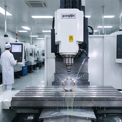
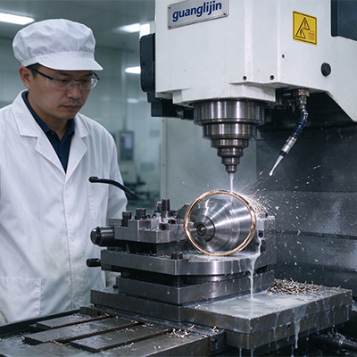
High-precision aerospace machining on a router platform sounds like a contradiction. Routers carry a reputation for rough trimming, not tight tolerance. That reputation is outdated. A properly specified cnc router 5 axis system holds aerospace trim tolerances when the gantry, control, and thermal strategy are built for the job. Here is how that works.
The Precision Gap: Why Routers Get a Bad Name
Most routers in service are built for signage, cabinetry, and general fabrication. Their gantries flex. Their controls lack five-axis compensation. Their spindles overheat on long cycles. Aerospace buyers who sample that market walk away unimpressed.
The precision gap is real, but it is a specification problem, not a platform problem. A router built to aerospace standards shares more with a gantry machining center than with a cabinet router. The difference sits in the structure, the control, and the thermal design.
Therefore, the first step in any precision router project is separating aerospace-grade platforms from general-purpose machines. Ask for gantry stiffness data, RTCP documentation, and thermal test reports. Without those three, the machine is not an aerospace solution.
Gantry Stiffness: The Foundation of Router Precision
A router gantry spans a wide work area. That span creates a lever arm. When the cutter loads the spindle, the gantry deflects. The deflection shows up as a wandering trim line and inconsistent depth.
Stress-relieved steel weldments provide the stiffness aerospace trimming demands. FEA-optimized geometry distributes material where the bending load is highest. Internal ribs stiffen the beam without adding excess mass.
The Z-axis column matters too. Deep molds put the spindle far from the gantry beam. A flexing column produces depth variation across the part. Precision-machined mounting plates and internal bracing control that flex.
Precision linear guideways and preloaded ballscrews close the loop. A rigid gantry on loose guides still moves. Specifying preloaded roller guides on the gantry and a ground ballscrew on the Z axis holds the geometry together.
Comparing Two High-Precision Router Solutions: Project A vs. Project B
| Parameter | Project A: Aerospace-Grade Platform | Project B: General-Purpose Platform |
|---|---|---|
| Gantry construction | Stress-relieved steel, FEA-optimized | Welded aluminum, minimal stress relief |
| Guideways | Preloaded roller guides on gantry | Standard ball guides |
| Control | RTCP active, five-axis compensation | Basic interpolation, no RTCP |
| Spindle | Liquid-cooled, thermal-stable | Air-cooled, torque drops with heat |
| Trim accuracy on 4 m panel | ±0.15 mm | ±0.6 mm |
| Surface finish on composite | Clean edge, minimal fuzz | Delamination and fuzz at corners |
Project A specified the aerospace-grade platform. Project B bought the general-purpose machine at lower cost. Project B’s first production run failed inspection on trim tolerance. The rework cost exceeded the purchase difference. Precision is a specification decision, not a marketing claim.
RTCP and Five-Axis Control: The Precision Enabler
RTCP keeps the tool tip on the programmed path as the spindle head tilts and swivels. Without it, every angle change shifts the tool tip by the pivot distance. The error grows with the pivot distance and the tilt angle.
Precision aerospace work needs more than basic RTCP. Look for tool center point management that accepts measured pivot errors and corrects for them. That function removes a manual touch-off step and a common error source.
Kinematic compensation for the rotary head is the next layer. The controller should model the head’s geometry and correct for angular positioning error. A well-compensated head holds a trim line across the full range of tilt angles.
The CAM side matters equally. Full machine simulation checks the tool path against the gantry, the head, and the table. Tool axis control lets the programmer set lead and lag angles along the path. That control produces a cleaner edge on composite panels.
Thermal Stability on Long Aerospace Cycles
Aerospace trim cycles run long. A large fuselage section may take hours to trim. Over that time, the spindle and the ballscrews heat up. The tool tip drifts.
Liquid-cooled spindles maintain torque and position through long cycles. Air-cooled spindles lose torque as the housing temperature climbs. The torque loss shows up as inconsistent feed and a rougher edge.
Our team measured thermal drift on a gantry router in 2025 during a six-hour composite trim cycle. The Z-axis ballscrew grew 28 µm. The spindle housing rose 9°C. The combination shifted the trim line by 0.18 mm over the cycle. Adding ballscrew cooling and spindle temperature compensation cut the drift to under 0.05 mm.
Research on machine tool thermal error supports the scale of this effect. Thermal errors account for 40–70% of total machining error on precision machine tools, per work published in CIRP Annals. The router platform is not immune. Thermal design belongs in the specification, not in the afterthought column.
Step-by-Step: Commissioning a Precision Router for Aerospace Trim
- Verify gantry and column stiffness. Ask for FEA results and stress relief documentation. Measure deflection with a dial indicator under a known load.
- Confirm RTCP and kinematic compensation. Check that the control accepts measured pivot errors and applies correction.
- Run a warm-up cycle. Bring the spindle and ballscrews to working temperature before any precision cut.
- Map thermal drift. Cut a test panel cold and again after four hours. Measure the trim line difference.
- Apply thermal compensation. Load the measured coefficients into the controller and verify with a second test panel.
- Cut a full-scale test part. Use the actual material and trim path. Measure on a CMM against the drawing.
Dust, Static, and Long-Term Precision
Carbon fiber dust is conductive and abrasive. It settles on guideways and ballscrews. Over months, it accelerates wear and degrades precision. A dust system sized for continuous operation protects the machine’s accuracy as much as the operator’s health.
Grounding and ionizers control static. Static discharge damages composite surfaces and attracts dust to the machine. Ground the fixture and the frame. Neutralize charge on the part before trimming.
Preventive maintenance keeps precision alive. Clean and re-grease the guideways on schedule. Check ballscrew backlash quarterly. Replace dust collector filters before they clog. A precision router stays precise when the shop maintains it.
Frequently Asked Questions
Can a 5-axis CNC router hold aerospace machining tolerances?
An aerospace-grade router with a stress-relieved steel gantry, preloaded roller guides, RTCP, and thermal compensation holds ±0.15 mm on large composite panels. Tighter features within ±0.02 mm usually need a machining center.
What gantry stiffness do I need for high-precision aerospace trimming?
Ask for FEA results and stress relief documentation. Measure deflection under a known load at the spindle nose. A precision router holds deflection under 0.05 mm for typical composite cutting loads.
How does RTCP improve trim accuracy on a 5-axis router?
RTCP keeps the tool tip on the programmed path as the head tilts. Without it, every angle change shifts the tool tip by the pivot distance. Advanced RTCP also accepts measured pivot errors and corrects for them.
How much thermal drift occurs on a 5-axis router during long cycles?
Field measurement showed 28 µm of Z-axis ballscrew growth and a 9°C spindle housing rise over six hours. Combined drift reached 0.18 mm. Ballscrew cooling and spindle compensation cut that to under 0.05 mm.
Why does carbon fiber dust reduce router precision over time?
Carbon fiber dust is conductive and abrasive. It settles on guideways and ballscrews and accelerates wear. A continuous-duty dust system, grounding, and scheduled cleaning protect long-term accuracy.
High-Precision Router Solutions Checklist
- Confirm stress-relieved steel gantry construction with FEA documentation.
- Verify preloaded roller guides on the gantry and a ground ballscrew on Z.
- Confirm RTCP and kinematic compensation are active in the control.
- Specify a liquid-cooled spindle with stable torque at working rpm.
- Run a warm-up cycle before any precision trim cut.
- Map thermal drift over a four-to-six-hour cycle.
- Load thermal compensation coefficients and verify with a test panel.
- Cut a full-scale test part and measure on a CMM.
- Start the dust collector and verify suction before cutting.
- Ground the fixture and frame to control static discharge.