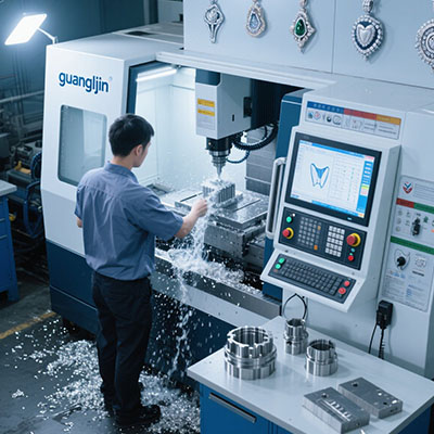
Industrial workpieces are heavy, large, and often hard to fixture. The Z axis carries the spindle over them, cutting deep pockets and long walls. When the Z axis is unstable, the whole cut suffers. Chatter appears on the walls. Depth varies across the part. Tool life drops. A stable z axis cnc solution attacks the source, not the symptom.
The Stability Problem: Load, Gravity, and Heat
The Z axis works against gravity all day. It lifts the spindle head, holds it during cutting, and lowers it on retract. That constant load changes the friction signature compared to the X and Y axes.
Cutting force adds to the load. A heavy roughing pass pushes the tool into the material. The reaction force travels up the spindle and into the Z column. A flexible column deflects and lets the tool chatter.
Heat adds the third load. The ballscrew and spindle warm during cutting. The screw grows. The tool tip drops. The depth changes mid-cut. A stable solution manages all three loads together.
Rigidity: Column and Guideway Choices
Column rigidity sets the ceiling for Z axis stability. A box column with internal ribs resists deflection better than a thin-walled column. Cast iron damps vibration better than welded steel.
Guideway choice matters too. Box ways offer large contact area and high damping. Linear guides offer speed and less damping. For heavy industrial cutting, box ways on the Z axis hold up better.
Some builders fill the column with polymer concrete. The fill adds mass and damping without adding cost. The natural frequency rises above the tooth-passing frequency. The chatter window narrows.
Therefore, the stable Z axis starts with the structure. Column mass, guideway damping, and spindle interface set the baseline. The control and the thermal plan build on that baseline.
Comparing Two Industrial Z Axis Solutions: Project A vs. Project B
| Parameter | Project A: Box Column, Box Way | Project B: Thin Column, Linear Guide |
|---|---|---|
| Column construction | Cast iron, ribbed, polymer-filled | Welded steel, thin wall |
| Z guideway | Box way with high damping | Linear guide, low damping |
| Counterbalance | Hydraulic, pressure-regulated | Pneumatic, basic |
| Chatter in heavy roughing | Minimal | Visible marks on walls |
| Depth variation over 4 hours | 9 µm | 27 µm |
| Tool life per edge | 34 parts | 23 parts |
Project A invested in column mass and damping. Project B saved on structure and lost it on chatter and tool life. Industrial workpieces reward the stable platform.
Counterbalance and Gravity Compensation
The counterbalance holds the spindle head against gravity. A weak counterbalance lets the head drop when the brake releases. A strong one lifts the head. Either way, the servo fights the imbalance.
Hydraulic counterbalance with pressure regulation holds the head steady. Set the pressure to match the head weight. Verify by disabling the servo and watching for drift. A head that holds position with the servo off has the right pressure.
Some machines use a pneumatic counterbalance. It costs less and holds less precisely. For heavy industrial heads, hydraulic is the better choice.
Our team adjusted counterbalance pressure on a heavy industrial machine in 2025. The head had been drifting 40 µm on brake release. Setting the pressure to match the head weight cut the drift to under 5 µm. The servo load dropped, and the Z axis ran cooler.
Thermal Control on the Z Axis
The Z axis ballscrew sits near the spindle motor and the cutting zone. Heat flows in. The screw grows. The tool tip drops. A machine that held tolerance cold may drift warm.
Ballscrew cooling pulls heat out of the screw. A chiller circulates oil through the nut housing or a hollow screw. The screw stays close to ambient temperature. The drift shrinks.
Thermal compensation in the controller corrects the remaining drift. The controller reads the screw temperature and adjusts the Z position. The correction is small but continuous.
Research on vertical machining centers shows that thermal error on the Z axis is a major contributor to depth variation. Work published in CIRP Annals reports thermal errors account for 40–70% of total machining error on precision machines. On heavy industrial cuts, the heat load is higher and the drift is larger.
Step-by-Step: Stabilizing the Z Axis for Industrial Cutting
- Check column rigidity. Measure deflection at the spindle nose under a known load. A flexible column needs bracing or replacement.
- Set the counterbalance pressure. Match it to the head weight. Verify drift with the servo disabled.
- Measure Z axis backlash. Target under 3 µm. Adjust the ballscrew nut preload in small increments.
- Map thermal drift. Cut a test part cold and again after four hours. Measure the depth difference.
- Install ballscrew cooling and thermal compensation. Load the coefficient and verify with a second test part.
- Keep tool overhang short. Long tools deflect under load and add to the instability.
- Run a heavy test cut. Cut the material and depth of the production job. Listen for chatter and measure the wall.
Servo Tuning for Stability, Not Speed
The servo controls the Z axis motion. High gain produces fast response and oscillation. Low gain produces slow response and following error. The right setting sits between the two.
For heavy industrial cutting, stability beats speed. Reduce the Z axis acceleration to 0.5–0.8 G. The cycle time difference is small. The motor runs cooler. Position overshoot at the end of a retract disappears.
Check the following error during a heavy cut. A large following error means the servo cannot keep up with the load. Raise the gain slightly or reduce the acceleration. Test after each change.
The z axis cnc solution for industrial workpieces is a system: structure, counterbalance, thermal control, and tuning. Each layer supports the others. A shop that plans the system gets stable cuts. A shop that skips a layer gets chatter and scrap.
Frequently Asked Questions
Why does my Z axis chatter during heavy industrial cutting?
The column may be flexing under load. The counterbalance may be set wrong. Backlash or thermal drift may be present. Check column deflection, counterbalance pressure, and backlash before tuning the servo.
How do I set counterbalance pressure on a Z axis CNC machine?
Match the pressure to the spindle head weight. Disable the servo and watch for head drift. A head that holds position has the right pressure. Adjust in small increments and verify each time.
What causes Z axis depth variation on industrial workpieces?
Ballscrew thermal growth, backlash, spindle growth under load, and tool deflection. Ballscrew cooling and thermal compensation reduce the thermal share. Backlash adjustment handles the lost motion.
Should I use a box way or linear guide on the Z axis for heavy cutting?
Box ways offer larger contact area and higher damping. They suit heavy roughing and interrupted cuts. Linear guides offer speed with less damping. For heavy industrial workpieces, box ways are usually the better choice.
How much Z axis backlash is acceptable for stable cutting?
Target under 3 µm for stable cutting. Higher backlash produces depth steps on every direction change. Measure with a dial indicator on the spindle nose and adjust the nut preload in small increments.
Stable Z Axis Industrial Cutting Checklist
- Measure column deflection at the spindle nose under load.
- Confirm the Z guideway type suits heavy cutting.
- Set counterbalance pressure to the head weight.
- Verify head drift with the servo disabled.
- Measure Z axis backlash and target under 3 µm.
- Map thermal drift over a four-hour cycle.
- Install ballscrew cooling and enable thermal compensation.
- Reduce Z acceleration to 0.6 G for heavy cuts.
- Keep tool overhang short for the cavity depth.
- Run a heavy test cut and measure the wall.