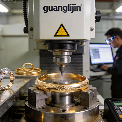
Aerospace manufacturing does not forgive approximation. A bracket that fits on the bench may fail under vibration. A bore that measures correctly at 20°C may drift at 35,000 feet. The 9 axis CNC machine exists because conventional platforms hit a wall. That wall is not about power or speed. It is about reach, datum integrity, and the number of times a part must be touched before it is finished.
What Separates Expert Aerospace Machining from General CNC Work?
Expert aerospace machining starts with a different question. The general shop asks: can we cut this feature? The aerospace shop asks: can we cut every feature without losing the datum? That distinction drives machine selection.
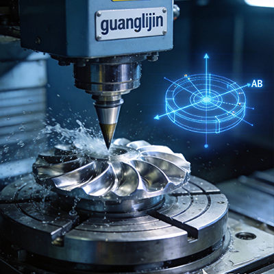
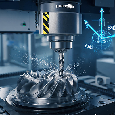
A 9-axis platform carries three linear axes and up to six rotary motions on one kinematic chain [citation:3]. The extra rotaries are not decoration. They allow the tool to approach a surface from an angle that a 5-axis trunnion cannot reach without re-fixturing. On a titanium structural fitting with cross-drilled ports on four faces, that capability eliminates three separate setups. Each eliminated setup removes a source of dimensional drift.
The tolerance claim matters here. Well-maintained 9-axis platforms hold ±0.005 mm on contoured surfaces [citation:3]. Some aerospace suppliers advertise ±0.0005 inch on parts up to 48 inches [citation:2]. Those numbers are not universal. They depend on thermal control, tooling, and the programmer’s understanding of how rotary error stacks as the part turns.
How Rotary Axis Placement Affects Cutting Mechanics
Not all 9-axis configurations behave the same. The location of the rotary axes changes the stiffness loop between tool and workpiece. A B-axis head mounted far from the part creates overhang. Overhang invites chatter. Chatter ruins surface finish and shortens tool life.
A compact design with the rotary axis directly under the part keeps the setup stiff. That stiffness matters for thin-wall aerospace components. Titanium Ti-6Al-4V deflects under cutting force. A stiff loop reduces that deflection. A loose loop amplifies it.
Thermal behavior follows the same logic. Six rotary axes mean more servos, more friction, and more heat near the cutting zone [citation:3]. On long aluminum runs, growth in the tenths of a millimeter range is possible without a warm-up cycle. Expert shops run a 15 to 30 minute warm-up before the first tight cut. This is standard practice, not optional insurance.
Project Comparison: Standard 5-Axis vs. Expert 9-Axis Setup
| Machining Factor | Project A: 5-Axis Milling | Project B: 9-Axis Mill-Turn |
|---|---|---|
| Typical part | Aluminum access panel | Inconel valve body with angled ports |
| Setup count | 3 | 1 |
| Datum references | Multiple, with regression risk | Single datum throughout |
| Angled feature access | Requires re-fixturing | Simultaneous rotary motion |
| Thermal exposure | Part cools between setups | Continuous cut, controlled temperature |
| Tolerance achieved | ±0.01 mm typical | ±0.005 mm or tighter |
| Scrap risk | Higher on final features | Lower, because features finish in one pass |
Project B wins on quality. Project A wins on simplicity. The expert aerospace shop knows which project belongs on which machine. Sending a simple bracket to a 9-axis center wastes machine time and programming hours. Sending a complex valve body to a 5-axis mill invites tolerance stack-up that no amount of inspection can fix.
⚠ Attention: Where Expert 9-Axis Machining Goes Wrong
⚠ Attention: The post-processor is the silent failure point. A CAM system that cannot interpolate nine axes simultaneously will produce a toolpath that looks correct on screen but drives the machine into a soft limit mid-cut. We saw this in a 2025 project involving a thin-walled titanium housing. The simulation passed. The real cut failed. The post-processor treated two redundant axes as static. The fix required a custom post revision, not a machine adjustment.
⚠ Attention: Chip evacuation becomes nonlinear with more axes. In deep pocket work approached from multiple angles, gravity does not clear the chips. Coolant through the spindle helps. But the programmer must plan entry and exit vectors with chip flow in mind. A perfect toolpath that buries chips will break tools.
⚠ Attention: Axis count does not equal capability. Some machines count the bar feeder and sub-spindle indexer as axes. Those axes position, they do not cut simultaneously [citation:3]. A buyer who assumes nine axes means nine simultaneous cutting motions will be disappointed. The practical test is simple: ask how many axes interpolate at the same time during a contouring move.
Step-by-Step Guide: Expert Setup for Aerospace 9-Axis Work
Step 1: Map every feature to an axis requirement. List each surface, hole, and contour. Note which features require angular access beyond the two rotaries of a 5-axis machine. If fewer than a quarter of features demand the extra axes, the part may not justify the platform.
Step 2: Validate the post-processor with a full collision simulation. Run the complete toolpath with all nine drives active. Check stroke limits, rotary travel, and interference between the head, fixture, and part. A simulation that skips the redundant axes is not a simulation.
Step 3: Design workholding that clears the rotary envelope. Low-profile modular fixturing keeps the part accessible. Simulate the full tilt range with the workpiece model loaded. A fixture that blocks the B-axis travel defeats the machine’s purpose.
Step 4: Establish thermal equilibrium before the first tight cut. Run the spindle warm-up cycle. Measure a reference feature. Run the cycle again. If the measurement moves, the machine is not ready for aerospace tolerances. KGL Precision runs their aerospace cell at 20 ± 0.5 °C for this reason.
Step 5: Verify with independent metrology. The machine probe is a production tool, not an inspection authority. Run the first article on a CMM. Compare the results to the digital model. If deviation exceeds half the tolerance band, stop. Investigate thermal compensation or post-processor accuracy before running production.
Frequently Asked Questions About 9 Axis CNC Aerospace Machining
Q: What aerospace parts actually justify a 9 axis CNC machine instead of 5-axis?
A: Parts with features on five or more faces that must share one datum. Hydraulic manifolds with cross-drilled ports on multiple sides fit. Impellers with twisted blades fit. A flat bracket with holes on two faces does not. The test is whether the extra axes eliminate setups on the specific part print [citation:3].
Q: Can a 9 axis CNC machine hold aerospace tolerances on titanium and Inconel?
A: Yes, with thermal control and a validated post-processor. Suppliers report ±0.0005 inch capability on parts up to 48 inches [citation:2]. The qualifier is “with thermal control.” A machine rated at ±0.005 mm in a temperature-controlled lab will not hold that tolerance in a shop that swings five degrees across a shift.
Q: What is the difference between 9-axis simultaneous machining and 9-axis positioning?
A: Simultaneous machining means the axes interpolate together while cutting. Positioning means the axes move to a location and lock before cutting begins. Positioning is useful for setup reduction. Simultaneous motion is what enables contoured surfaces and angular features in one pass. The two capabilities carry different price tags and different programming demands [citation:3].
Q: How long does it take to program a 9-axis aerospace part compared to a 5-axis part?
A: Programming time increases with axis count, but the net production time often decreases because setups disappear. The real learning curve is in the post-processor and the operator’s understanding of coordinate systems. Shops that invest in training and a validated post see the programming penalty shrink after the first few parts.
Checklist: Expert 9-Axis Aerospace Machining Readiness
☐ Feature-to-axis mapping completed — extra axes justified by datum consolidation or angular access
☐ Post-processor validated with full nine-axis collision simulation
☐ Workholding designed to clear the complete rotary envelope
☐ Thermal warm-up cycle documented and followed before first article
☐ CMM inspection plan approved and independent of machine probe
☐ Chip evacuation strategy reviewed for multi-angle deep pocket work
☐ Operator trained on nine-axis coordinate systems and recovery procedures
☐ Rotary axis calibration and linear scale verification scheduled
☐ First article deviation reviewed against tolerance band before production release
The expert aerospace shop does not buy a 9 axis CNC machine because it sounds advanced. It buys the machine because a specific part cannot be made another way without sacrificing datum integrity or accepting scrap risk. The machine is a tool. The expertise is knowing when to use it, how to program it, and when to leave it idle while a simpler platform runs the simple work.