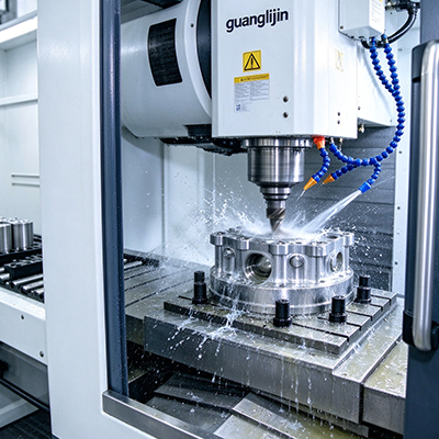
SEO Description: Precision cnc 3 axis mill systems for aerospace parts. Thermal control, probing, and rigidity data inside.
An aerospace print arrives with a true-position callout of 0.025 mm across a 600 mm bulkhead. The tolerance is not the problem. Holding it for eight hours while the spindle heats and the ballscrews grow is the problem. Precision three-axis systems earn their price on that single capability: staying in tolerance when conditions change.
Generic vertical mills quote positioning accuracy at 20°C in a laboratory. Aerospace shops run 24/5 in rooms that drift. The gap between catalog numbers and shop-floor results defines which systems deserve the precision label.
What Precision Actually Means on the Shop Floor
Positioning accuracy describes a single move. Aerospace work demands more. It demands repeatability across thousands of cycles. It demands thermal stability over a full shift. It demands contouring accuracy under load while the cutter pushes back.
Linear glass scales close the loop on actual axis position. A machine with rotary encoders on the ballscrew measures screw rotation, not table position. Ballscrew thermal growth introduces error the encoder cannot see. Glass scales read the table directly. That distinction separates precision platforms from standard ones.
Structural damping matters equally. A cast iron bed absorbs vibration that a fabricated steel frame transmits. In titanium roughing, that difference shows in tool life and surface finish. The DNM 6700 series uses a rigid cast structure with 1,300 kg table capacity for this reason . The Haas HDC-3 pushes that further with a 4,536 kg table for large airframe sections .
Comparison: Two Precision Routes for Aerospace Shops
| Specification | Project A: Vertical Precision Mill | Project B: Double-Column Bridge Mill |
|---|---|---|
| Architecture | C-frame vertical, moving table | Double-column, fixed bridge |
| Table Capacity | ~1,300 kg | ~4,536 kg |
| Best For | Brackets, fittings, housings | Wing ribs, bulkheads, long sections |
| Thermal Strategy | Active compensation, warm-up cycle | Symmetrical structure, cooled ballscrews |
| Probing Integration | Spindle-mounted touch probe | Table-mounted and spindle probe |
| Footprint | Moderate | Large |
| Typical Investment | $120k–$250k | $350k–$700k+ |
| Setup Complexity | Moderate | High; foundation and leveling critical |
Project A suits a shop running varied aerospace work in moderate batch sizes. Project B rewards manufacturers with stable contracts on large structural parts. The double-column architecture puts the cutting force into a closed frame. That rigidity shows up in surface finish on deep pockets and long walls.
However, the bridge mill demands a proper foundation. Thermal symmetry disappears if the machine sits on a floor with a temperature gradient. Precision without installation discipline is a brochure claim.
Step-by-Step: Commissioning a Precision Three-Axis System
- Level and Anchor Before Power-Up. Precision begins with the foundation. Use a precision level at multiple points on the table. Check for twist across the full travel. Anchor bolts torqued to specification prevent vibration from walking the machine out of alignment over months of operation.
- Run a Thermal Warm-Up Protocol Daily. Spindle and ballscrew growth follow predictable curves. A 20–30 minute warm-up cycle at production speeds stabilizes temperatures before the first cut. Document the warm-up program. Treat it as part of the process, not an optional ritual.
- Verify Squareness and Geometry With a Ballbar. A ballbar test reveals servo mismatch, squareness error, and backlash in a single circular test. Run it at commissioning and monthly thereafter . Trend the results. A change in the ballbar plot signals wear before scrap appears.
- Calibrate the Probe Against a Master Artifact. The touch probe is only as accurate as its calibration. Use a certified sphere or ring gauge. Verify probe repeatability in all three axes. An uncalibrated probe introduces error into every work offset the machine uses.
- Establish Thermal Compensation Offsets. If the control offers active thermal compensation, verify it against measured part growth. Cut a test part, measure it cold and hot, and compare. Tune the compensation model until measured growth matches predicted growth.
- Probe the Part After Roughing. Roughing generates heat and relieves residual stress. The part moves. Probe critical datums after roughing and update work offsets before finishing. One aerospace shop cut scrap by 33% in 2025 with this single step .
Mistakes That Defeat Precision Systems
⚠ Attention: Avoid assuming glass scales eliminate thermal error. Scales read table position accurately, but the workpiece grows with temperature too. A part that measures 0.020 mm oversize at 26°C may be perfect at 20°C. Measure at the temperature your print specifies, or apply thermal correction to the measurement.
We worked with a Tier 2 aerospace supplier in 2025 that fought a persistent taper problem on aluminum ribs. The machine passed ballbar and laser interferometer tests. The culprit was fixture clamping sequence. Clamping one end first tilted the part 15 microns before the second clamp engaged. Changing to simultaneous hydraulic clamping removed the taper. The machine was never the problem. The setup was.
Another common error involves tool setting. Laser tool setters measure length to a few microns. Touching off on a workpiece surface introduces variation from surface finish and contact pressure. For precision aerospace work, use a laser or contact presetter, not the part surface.
Probing and In-Process Verification
Precision without verification is faith. Aerospace shops verify. Spindle-mounted touch probes check critical features during the cycle. If a pocket is 0.015 mm off, the machine can adjust the wear offset for the next part before the first one is scrapped.
Table-mounted probes add another layer. They check the fixture and the part datum before cutting begins. A fixture that shifted between shifts shows up immediately. The operator corrects the offset before the tool touches metal.
Data logging turns probing into a trend. Store every measurement. Plot the results over weeks. Thermal drift, wear, and fixture degradation appear as slow curves, not sudden failures. The best cnc 3 axis mill systems make this data accessible through the control. Shops that use it catch problems while they are still cheap.
Frequently Asked Questions
Q: What positioning accuracy should I look for in a precision 3-axis CNC mill for aerospace?
A: Look for repeatability of 0.005 mm or better and positioning accuracy of 0.010 mm across the full travel. Verify these numbers on your floor, not just the spec sheet. Linear glass scales, active thermal compensation, and a rigid cast structure support that level of precision.
Q: How does thermal growth affect 3-axis CNC machining accuracy?
A: Spindle and ballscrew temperatures rise during operation. That growth shifts the tool tip relative to the part. A 3°C rise in a 500 mm ballscrew can move the table by tens of microns. Warm-up cycles, active compensation, and probing after roughing manage the effect.
Q: Why do aerospace shops use touch probes on 3-axis CNC mills?
A: Probes verify part position, fixture location, and critical features during the cycle. Post-roughing probing captures thermal growth and stress relief movement. Data logging turns probe results into trend analysis. This prevents scrap before it happens .
Q: Can a vertical 3-axis mill hold aerospace tolerances on large bulkheads?
A: A well-built vertical with glass scales, thermal compensation, and adequate table capacity handles medium bulkheads. Very large structural sections benefit from a double-column bridge mill where the closed frame resists deflection across long spans. Match the architecture to the part envelope.
Precision is not a specification. It is a practice. A rigid platform with closed-loop feedback provides the foundation. Thermal discipline, probe verification, and data trending turn that foundation into parts that pass inspection every shift. The best 5 axis cnc headlines grab attention. The three-axis systems behind them hold the tolerance.
✅ Precision Three-Axis System Verification Checklist
- Foundation leveled and anchor bolts torqued to specification
- Floor vibration measured before installation
- Daily warm-up protocol documented and followed
- Ballbar test completed at commissioning and scheduled monthly
- Linear glass scales verified and functioning on all axes
- Touch probe calibrated against certified master artifact
- Thermal compensation model tuned against measured part growth
- Probe cycle scheduled after roughing for offset correction
- Tool setting done with laser or presetter, not part surface
- Clamping sequence reviewed for part distortion
- Measurement data logged and trended over time
- Part measured at print-specified temperature
Data sources: DN Solutions DNM series technical specifications ; Haas Automation HDC-3 specifications ; aerospace machining process guidance (2025) .