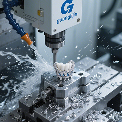
Aerospace buyers rarely fail because they picked the wrong brand. They fail because they never tested the machine against their hardest part. Thin walls deflect. Compound angles drift. Inspection reports come back red. This guide tackles that exact failure mode. We show how to evaluate a precision 5-axis cnc mill for aerospace parts, which specifications actually predict success, and how to prove capability on your alloy before committing capital.
What Precision Really Means on an Aerospace Mill
Precision is not one number. It is a behavior under load, across a shift, through a temperature swing. A machine may position to ±0.005 mm at rest. Feed it titanium and the story changes. Spindle growth, axis thrust, and chip load all shift the cutting edge.
Therefore buyers must separate static accuracy from dynamic capability. Static numbers come from a calibration certificate. Dynamic capability comes from a test cut on your material. Only one of those predicts inspection results.
Tool-center-point control belongs in this discussion. Without RTCP, the rotary axes move the tool tip off its programmed path. Compound-angle aerospace features fail. Free-form surfaces ripple. A machine without true TCP is a three-axis platform with a tilting accessory.
Our team found in a 2025 aerospace program that a mill held tolerance on a small bracket for six hours. It drifted on a thin-wall housing after hour nine. The spindle housing had warmed by 4 °C. Probe compensation every twenty parts recovered the run. Precision, in practice, is a schedule, not a badge .
Project A vs Project B: Aerospace Build Comparison
Two suppliers bought precision mills for aerospace contracts. Project A chose a high-speed trunnion platform. Project B selected a box-way machining center with a swivel head. Their part families diverged, and so did their scrap rates.
| Factor | Project A — High-Speed Trunnion | Project B — Box-Way Swivel Head |
|---|---|---|
| Typical part type | Small precision brackets, housings | Larger structural parts, molds |
| Spindle speed range | High RPM, aluminum-focused | Wide torque band, alloy-flexible |
| Rigidity profile | Excellent at light cuts | Strong under heavy radial load |
| Thermal management | Spindle chiller plus probe compensation | Coolant-through-spindle, heavier mass damping |
| Setup count | 1–2 with probing | 1 on fixed bed |
| Best fit | High-mix precision components | Heavy cuts in tough alloys |
Project A excelled on aluminum brackets with tight true position. Project B held form on titanium structural parts where radial loads run high. However, Project B lost time on small features because its spindle topped out lower. The comparison forces a question: which alloy drives your revenue?
Five Steps to Validate a Precision Aerospace Mill
Do not accept a demo on scrap aluminum. Do not trust a certificate alone. Run this sequence with your hardest alloy and your tightest feature.
Step 1: Demand a Simultaneous Five-Axis Cut on Your Alloy
Provide a test file with compound angles and a thin-wall section. Watch the tool tip on the control display. It should track the path without hesitation. Listen for spindle load spikes at direction changes. Titanium and stainless expose weakness that aluminum conceals. Measure true position and finish afterward.
Step 2: Verify RTCP Under Continuous Motion
Ask for a test that tilts the head through a continuous arc while cutting. Without RTCP, the tool tip drifts and the feature fails. Request sample G-code. Look for simultaneous rotary and linear commands. Indexed output disguised as multi-axis will not hold aerospace surfaces .
Step 3: Stress-Test Thermal Stability
Run the machine for thirty minutes at production load. Then cut a test feature and measure it. Repeat after another thirty minutes. A stable machine holds size between runs. A drifting machine reveals itself here. Aluminum expands about 23 microns per meter per degree Celsius . Thermal compensation is not optional for tight aerospace work.
Step 4: Match Spindle Torque and Cooling to Your Alloy
Aluminum rewards high RPM. Titanium and Inconel demand torque at the cutting edge. Ask for the torque curve at your cutting speed, not the peak rating. Then confirm cooling. Through-spindle coolant extends tool life in tough alloys. Air blast alone falls short on deep pockets.
Step 5: Audit the Post-Processor and Probing Routine
A precision mill without a capable post wastes its rotary axes. Ask the vendor to post your test geometry through their recommended CAM output. Inspect the code for continuous motion. Then review the probing strategy. In-process verification catches drift before scrap. Without it, operators guess offsets and ruin expensive billet.
Common Mistakes in Aerospace Mill Selection
⚠Attention: Do not specify a machine for your average tolerance. Specify it for your tightest tolerance, then prove it statistically over a full shift. A certificate at ±0.005 mm says little about hour nine.
⚠Attention: Do not ignore workholding for thin-wall parts. A fixture that clamps a thick bracket will distort a thin frame. Plan supports and clamping force for the actual part stiffness.
⚠Attention: Never skip warm-up on tight-tolerance work. A cold spindle grows as it heats. Run the full motion range for thirty minutes before first article. Probe critical features on a fixed schedule .
Another quiet error involves the inspection environment. A mill that holds ±0.003 mm in a climate-controlled bay may fail when parts cool on an open floor. Match the shop environment to the tolerance, or plan for temperature soak before measurement.
Frequently Asked Questions
What accuracy does a precision 5-axis CNC mill need for aerospace parts?
Critical aerospace features often target ±0.0002″ (about ±0.005 mm), with some bearing bores tighter . Achievable results depend on thermal control, probing frequency, and machine rigidity. Always request a test cut on your alloy.
Is a high-speed spindle or a high-torque spindle better for aerospace?
It depends on the alloy mix. Aluminum favors high RPM with sharp tools. Titanium and stainless demand torque at the cutting edge. A wide torque band across speeds handles mixed work better than a peak-power spindle .
Why is RTCP critical for aerospace machining?
RTCP keeps the tool tip on its programmed path while the rotary axes move. Without it, compound-angle features and free-form surfaces drift. Aerospace parts rarely tolerate that drift .
How often should aerospace parts be probed on a 5-axis mill?
Production shops often probe critical features every twenty parts or every two hours, whichever comes first. Thermal drift and tool wear drive the schedule. Tighten the interval after any warm-up or tool change .
Can a 5-axis CNC mill cut titanium and Inconel?
Yes, with sufficient torque, rigid construction, and through-spindle coolant. Light machines chatter and burn tools in these alloys. Confirm the torque curve and coolant strategy before purchase .
Pre-Purchase Checklist
- ☐ Contract part envelope and alloy mix documented
- ☐ Tightest tolerance and surface finish requirement defined
- ☐ Simultaneous five-axis cut observed on your alloy
- ☐ RTCP verified under continuous motion
- ☐ Thermal drift tested over a thirty-minute run
- ☐ Spindle torque curve matched to alloy mix
- ☐ Through-spindle coolant capability confirmed
- ☐ CAM post verified for simultaneous output
- ☐ Probing schedule and in-process verification planned
- ☐ Workholding plan sketched for thin-wall parts
- ☐ Inspection environment and temperature soak defined
- ☐ Service access and spare spindle lead time verified