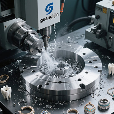
High accuracy does not come from the machine alone. It comes from the decisions made before the spindle turns. An expert 3 axis cnc design approach treats tolerance as a budget. Every setup, fixture, and tool choice spends part of that budget. Spend wisely, and the part passes first article. Spend carelessly, and scrap becomes the norm.
This article covers how expert-level 3-axis work achieves aerospace accuracy. It also covers where the approach breaks down and how to spot trouble early.
The Accuracy Problem: Why Good Machines Still Produce Bad Parts
A new 3-axis vertical mill holds ±0.005 mm positioning accuracy out of the box . That number looks impressive on a spec sheet. It rarely survives contact with a real aerospace job.
Why? Because positioning accuracy is not the same as part accuracy. Fixture deflection, tool deflection, thermal growth, and setup variation all eat into the tolerance budget. A machine with ±0.005 mm positioning can produce parts with ±0.08 mm true position error if the fixture flexes under cutting load.
Therefore, expert 3-axis machining focuses on the whole system. The machine is one variable. The fixture, the toolpath, the material, and the inspection plan are equally important. Control all five, and accuracy follows.
Project A vs. Project B: How Design Choices Drive Accuracy Outcomes
Two aerospace jobs can look similar on paper and behave very differently in the shop. The table below contrasts two real part profiles from aerospace subcontracting work.
| Variable | Project A: Actuator Mount Bracket | Project B: Hydraulic Valve Body |
|---|---|---|
| Feature Access | Two faces, parallel planes | Five faces, cross-drilled ports |
| Setup Count | 2 | 5 on 3-axis (or 1 on 5-axis) |
| Tolerance | ±0.05 mm | ±0.02 mm true position |
| Fixture Type | Standard vise with soft jaws | Custom multi-station tombstone |
| Thermal Risk | Low—short 14 min cycle | High—78 min cycle with warm-up drift |
| First-Pass Yield | 96% | 84% (improves to 92% with thermal compensation) |
| Accuracy Strategy | Standard process control | In-process probing and warm-up routine |
Project A rewards standard 3-axis practice. The bracket geometry is simple. Two setups cover every feature. The tolerance is achievable without heroics. Project B punishes 3-axis unless the shop invests in thermal control and probing. Each additional setup adds error. Five setups on a valve body demand tight discipline to hit ±0.02 mm.
Five Steps to Expert-Level Accuracy on 3-Axis Aerospace Parts
Accuracy is a process, not a personality trait. Follow these steps to build repeatable high-accuracy 3-axis machining.
Step 1: Map the Tolerance Budget Before Programming
List every critical feature and its tolerance. Allocate error budget across setups. A two-setup part with ±0.05 mm tolerance leaves ±0.025 mm per setup—comfortable. A five-setup part with ±0.02 mm leaves ±0.004 mm per setup—demanding. Know the math before quoting.
Step 2: Engineer the Fixture for Rigidity, Not Convenience
Every fixture deflects. The question is how much. A vise with soft jaws deflects less than a strap clamp on a thin wall. A tombstone with preloaded supports deflects less than a custom bracket bolted to the table. Measure fixture deflection under simulated cutting load during first article runs.
Step 3: Control Thermal Growth with Warm-Up Cycles
Spindles and ballscrews grow as they heat. A 3-axis mill running a 60-minute cycle can drift 0.008–0.015 mm from cold start to steady state . Run a 20-minute warm-up cycle before cutting critical features. Alternatively, probe the part at intervals and compensate.
Step 4: Use the Largest Cutter the Geometry Allows
Small cutters deflect. Deflection shows up as taper, chatter, and dimensional drift. A 12 mm end mill deflects far less than a 6 mm end mill at the same cutting load. Design internal radii to accept larger tooling where possible.
Step 5: Inspect In-Process, Not Just at the End
Final inspection catches problems after the value has already been added. In-process probing catches drift before it ruins the part. Probe critical features after each setup. Trend the results. Adjust offsets when the trend moves.
⚠ Attention: Accuracy Killers That Hide in Plain Sight
⚠ **Fixture clamping on a machined surface.** Clamping on a surface that later becomes a datum introduces error. The clamp pressure deforms the surface during machining. Once released, the part springs back. Machine the datum first, then clamp on it for subsequent operations.
⚠ **Ignoring tool wear on long runs.** A carbide end mill wears measurably after 40–60 minutes in titanium . The wear shows up as dimension drift before it shows up as poor finish. Change tools on a schedule, not on failure.
⚠ **Assuming coolant solves thermal problems.** Flood coolant helps, but it does not eliminate spindle growth. The spindle housing expands regardless of coolant flow. Warm-up routines and probing remain necessary.
Case Observation: What Our Team Found in 2025
Our team worked with an aerospace supplier last year on a series of 7075 aluminum housings. The parts had a ±0.025 mm true position callout on four mounting holes. The shop ran them on a 3-axis mill with two setups. Yield was stuck at 81%.
We audited the process and found the problem in setup two. The fixture clamped on a surface machined in setup one. Clamp pressure varied between operators. The variation showed up as hole position drift. We redesigned the fixture to clamp on a dedicated pad outside the tolerance zone. Yield rose to 95% within three production runs. The machine never changed. The expert 3 axis cnc design thinking changed the outcome.
When 3-Axis Accuracy Plateaus—and What to Do Next
There is a ceiling to 3-axis accuracy. It appears when setup count exceeds three or when true position demands fall below ±0.015 mm across multiple faces. At that point, the error budget per setup shrinks below practical control limits.
However, the ceiling is higher than many shops assume. With probing, thermal compensation, and rigid fixturing, a 3-axis mill can hold ±0.013 mm on a single setup. The limitation is process discipline, not axis count. Shops that invest in discipline beat shops that invest in machines without discipline.
Accuracy Checklist for 3-Axis Aerospace Machining
- ☐ Tolerance budget mapped per setup before programming
- ☐ Fixture deflection measured under simulated cutting load
- ☐ Warm-up cycle documented and followed before critical cuts
- ☐ Largest feasible cutter selected for every pocket and profile
- ☐ Datum surfaces machined before they are used for clamping
- ☐ Tool wear schedule defined for the material and cycle length
- ☐ In-process probing plan included in the process sheet
- ☐ Thermal drift trended across the first five production parts
- ☐ CMM inspection results reviewed against budget after first article
- ☐ Process sheet archived with actual feeds, speeds, and offsets used
Frequently Asked Questions
What accuracy can expert 3 axis CNC design achieve on aerospace aluminum parts?
A disciplined 3-axis process holds ±0.025 mm routinely on two-setup parts. Single-setup features can reach ±0.013 mm with probing and thermal control. Drawings calling for ±0.05 mm leave comfortable margin for standard process variation .
How do I choose between 3-axis and 5-axis for high accuracy aerospace machining?
Count the machining faces. Two faces with standard tolerances favor 3-axis. Three or more faces with true position tighter than ±0.025 mm favor 5-axis. The 5-axis machine eliminates setups, and fewer setups mean less accumulated error.
Why does my 3-axis machine drift during long aerospace cycles?
Thermal growth moves the spindle and ballscrews as the machine warms. A 60-minute cycle can drift 0.008–0.015 mm from cold start. Warm-up cycles, in-process probing, and offset compensation control the drift .
What fixture design improves accuracy on custom 3-axis aerospace parts?
Clamp on dedicated datum pads, not on functional surfaces. Use preloaded supports for thin walls. Measure fixture deflection under load. A rigid fixture with predictable clamping beats a convenient fixture with variable clamping every time.
Can 3-axis CNC design meet AS9100D accuracy and traceability requirements?
Yes. AS9100D governs the quality system, not the machine configuration. A documented 3-axis process with calibrated inspection, material traceability, and archived process sheets satisfies aerospace audit requirements. Simpler setups make documentation easier to maintain.