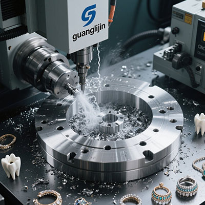
Choosing the right motion platform for a small industrial machine is stressful. You want precision, but budgets are tight. A 3 axis cnc controller kit servo solves this tension by bundling the controller, drives, and motors into one validated system.
What Does a Servo-Based 3-Axis Kit Actually Include?
A typical industrial kit is not just a breakout board. It ships with a motion controller, three servo drives, three AC servo motors, encoder cables, and power logic. SZGH, for instance, packages an 8.4-inch LCD controller with servo motors and braking resistors in a single cabinet-ready set [citation:1].
You also get the communication layer. Most modern kits support pulse/direction or analog signals. Higher-end sets add EtherCAT or Modbus for faster loop closure [citation:1][citation:6].
Specific components matter. A DMM plug-and-play example lists a 400W motor, a DYN2 drive, a 48V power supply, and a parallel breakout board. The total lands near $1,905 for three axes [citation:6]. That number gives you a realistic baseline.
Servo Kits vs. Stepper Kits: A Practical Comparison
Steppers are cheap and simple. Servos cost more but hold torque at speed and close the position loop. For industrial duty, the difference shows up in scrap rate and uptime.
| Project Factor | Project A: Stepper Kit | Project B: Servo Kit |
|---|---|---|
| Typical entry cost | ~$500–$700 | ~$1,300–$1,900 [citation:5][citation:6] |
| Position feedback | Open loop (no encoder) | Closed loop with encoder |
| Torque at speed | Drops sharply | Holds rated torque to base speed |
| Best for | Light routing, hobby retrofits | Industrial milling, repetitive production |
Therefore, if your machine runs eight hours a day, the servo premium pays back through fewer lost parts. If you prototype occasionally, a stepper set may suffice.
How to Install and Tune a 3-Axis Servo Kit: 5 Steps
Wiring errors cause most startup failures. Follow a fixed sequence and verify each stage.
Step 1: Mount Motors and Check Coupling Alignment
Bolt the servo motors to the frame. Use a dial indicator to verify coupling runout. Misalignment destroys bearings within weeks. Keep motor cables separated from encoder cables to avoid noise injection [citation:3].
Step 2: Wire Power and Logic Circuits Separately
Route 220VAC power to the drive main circuit. Feed 24VDC logic to the controller. Never bundle AC and encoder wires in the same conduit. Use shielded twisted pairs for encoder A/B channels and ground the shield at the drive end only [citation:3].
Step 3: Connect the Pulse/Direction or Bus Interface
For pulse control, wire STEP and DIR from the controller to the drive. For EtherCAT, daisy-chain the drives and set unique node addresses. Verify with the drive’s tuning software that commands reach the drive before enabling the motor.
Step 4: Run Auto-Tuning Without Load
Disconnect the motor from the screw. Execute the drive’s inertia identification routine. This step sets the velocity loop gain and filter parameters. Skipping it causes resonance or overshoot during acceleration.
Step 5: Validate Motion Under Load and Set Safety Limits
Reconnect the load. Jog each axis at 10% speed. Then test rapid moves and watch for following error. Finally, configure overtravel limits. The drive must force speed to zero when a limit switch triggers, with reverse motion still allowed [citation:9].
Another trap: connecting the servo enable signal to the wrong logic level. Some drives need 24VDC on ENA+, while others expect a sinking output. Check the drive manual twice.
Real-World Tuning Insight from Our Team
We ran into a resonance issue on a 3-axis router retrofit last quarter. The Y-axis howled at 40% rapid speed. Auto-tuning alone did not fix it. We lowered the velocity loop gain by 15% and enabled a notch filter at 180 Hz. The noise vanished, and positioning error dropped to ±0.02 mm.
That experience reinforced a simple rule: never trust default gains on a machine with a long screw. The load inertia changes with table position. Spend twenty minutes running a sweep test.
Another data point: a DMM kit with 400W servos holds 1.27 Nm continuously across the entire speed range [citation:6]. For comparison, a NEMA 34 stepper might deliver similar holding torque at standstill but lose over half of it by 600 RPM. That gap matters for drilling and tapping cycles.
Frequently Asked Questions
What is the difference between a 3 axis CNC controller kit with servo and a stepper kit?
A servo kit adds encoder feedback and closed-loop control. The drive corrects position errors in real time. Stepper kits run open loop and can lose steps under load.
Can I use a 3-axis servo kit for a lathe instead of a mill?
Yes, if the controller supports lathe-specific functions like spindle synchronization and tool offset tables. Verify the firmware mode before purchase. Some controllers are mill-only.
How much power do I need for a small industrial 3-axis servo setup?
A 400W-per-axis system with a 48VDC supply covers most benchtop mills. Heavier cuts demand 750W to 1.5kW drives and 220VAC input [citation:5]. Match the supply to the drive’s peak current, not just the motor rating.
Final Checklist Before Power-On
- ☐ Motor couplings aligned to under 0.05 mm runout
- ☐ Encoder cables shielded and separated from motor power
- ☐ Drive node addresses set correctly (for bus systems)
- ☐ Emergency stop wired to the controller’s hardware input
- ☐ Overtravel limits tested in both directions
- ☐ Auto-tuning completed without load connected
- ☐ First motion command tested at low speed and short distance
For teams sourcing a 3 axis cnc controller kit servo for industrial use, the checklist above prevents the most common failures. A validated kit with proper wiring and a conservative tuning pass will outperform a premium kit rushed into service.