Aerospace drawings are not gentle. A manifold with four angled ports. A collar with cross-drilled holes that must align with a sealing bore. One feature references another. The tolerance lives in that relationship.
Re-clamp the part and the relationship breaks. The fixture becomes the tolerance. A high performance 4 axis CNC lathe exists to keep the part in one chucking while the tool reaches every face.
Yet machine capability alone does not deliver aerospace tolerances. The process around the machine decides whether the fourth axis earns its keep.
Why Multi-Face Aerospace Parts Punish Re-Clamping
Consider an actuator end cap. It carries a bolt circle on one face and a sealing bore on the other. The drawing ties bolt-hole true position to the bore axis. Machine the bore in setup one and the bolt circle in setup two, and the chuck jaw error enters the tolerance stack.
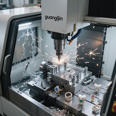
Single-setup machining removes that error path. Live tooling rotates the part to an indexed angle. The tool drills, mills, or taps without releasing the workpiece. The datum never leaves the chuck.
Therefore, the buying question is not axis count. It is whether the process can hold feature-to-feature relationships across a production lot. That is a different conversation.
Project A vs Project B: Two Strategies for the Same Drawing
| Factor | Project A: 3-Axis Plus Manual Flips | Project B: 4-Axis with Driven Tooling |
|---|---|---|
| Setup count | 3–4 re-clampings | 1–2 setups |
| Datum integrity | Error accumulates across flips | Datum held through single fixturing |
| Cross-feature access | Secondary mill required | Radial and axial live tools reach both faces |
| Cycle time | Handling adds hours | Floor-to-floor time drops with fewer touches |
| Best fit | One-face features, prototypes | Housings, fittings, multi-port brackets |
Project A works when all features sit on one face. The risk climbs the moment the drawing ties two faces together. No inspection plan fully recovers a datum that was released between operations.
Project B costs more upfront. The return arrives through scrap reduction and shorter setups. The DMG Mori NLX platform with driven tooling entered U.S. Navy repair depots for exactly this reason . The reported gains were fewer setups and tighter accuracy on aviation components.
However, the machine is only half the story. The CAM post and the fixture carry equal weight.
Step-by-Step: Validating the Process Before Cutting Metal
- Audit the drawing for angular relationships. List every feature that references another face. Radial ports, cross-holes, indexed flats, compound angles. If every feature lives on one face, the fourth axis adds cost without payoff.
- Request fixture photos and clamp force data. A supplier without workholding photos for a similar geometry is guessing. The fixture must locate on a stable datum and clamp without wall distortion. Clamp marks on finish surfaces signal hand blending later.
- Confirm the CAM post emits native rotary commands. Some legacy workflows swap the X axis for the rotary device and recalculate pulse equivalents by stock diameter. That trick collapses once simultaneous X and C motion is needed. The post must output true C or A commands.
- Demand angular true position in the first-article report. OD and length measurements do not validate a fourth axis. The report must show measured angular deviation on radial features relative to the primary datum.
- Run a coupon on the hardest feature. Same indexing, same tool reach, same tolerance band. Compare true position and surface finish against the drawing before releasing production.
- Lock the thermal plan for the alloy class. Titanium and Inconel move the part and the machine as they heat. The Hwacheon Hi-Tech 400 holds ±0.0005 inch on critical features in aerospace alloys, but only with documented thermal and tool-wear controls . Without that discipline, drift appears between the first and last part.
Case Notes: The Fixture Was the Variable
Our team reviewed a 2025 production run of 17-4 PH actuator sleeves. Each part needed six radial ports at 60-degree spacing plus a counterbore on the far face. The chosen 4 axis CNC lathe carried C-axis indexing and live tooling.
The first fixture used a three-jaw chuck on the sleeve OD. Ports landed within 0.012 mm of true position. The counterbore, cut after the ports in the same setup, showed 0.035 mm runout against the port pattern. The chuck had crushed the thin wall during clamping.
We moved to a custom expanding collet located on the bore and clamped from inside. Port position held within 0.010 mm. Counterbore runout fell to 0.008 mm. Same machine. Different workholding. Different result.
Frequently Asked Questions
Production-grade four-axis lathes with live tooling and C-axis indexing typically reach positioning accuracy near ±0.005 mm and repeatability around ±0.003 mm. Hwacheon’s Hi-Tech 400 claims ±0.0005 inch (0.0127 mm) routine tolerance on critical features in aerospace alloys . AS9100 work still demands thermal compensation, in-process probing, and documented tool-wear control.
Live tooling mills, drills, and taps at indexed angles without releasing the part. A fitting with face ports, radial cross-holes, and a sealing bore finishes in one chucking. The datum from the first operation stays valid for every later feature, which removes stack-up error from re-clamping .
Angular true position on radial features. C-axis index accuracy. Runout on turned diameters relative to the rotary datum. Surface finish on interpolated features. A report listing only OD and length has not validated the fourth axis at all.
Yes, with enough spindle torque and a thermal plan. Both alloys demand low RPM and high torque. Hwacheon’s heavy-duty configuration runs 1,800 RPM with box-way rigidity for these materials . Tool wear management, not axis capability, is usually the limit. Ask for documented tool life on the specific alloy and condition.
When clamping distorts the part, when jaws block feature access, or when volume passes 500 pieces. A custom expanding mandrel or dedicated collet system pays back through less scrap and no hand blending. The case above cut runout by 77% from a fixture change alone.
Checklist: Qualifying a High Performance Four-Axis Aerospace Partner
- Drawing audited for angular feature relationships before machine selection
- Fixture strategy documented with clamp force data and photos
- CAM post verified to emit native rotary commands, not axis swaps
- First-article report includes angular true position
- Thermal compensation plan documented for the alloy class
- Live tooling confirmed for both radial and axial operations
- Coupon cut on the hardest production feature before release
- Tool wear monitoring defined for titanium or Inconel runs
- Datum held across all operations without re-clamping
- Supplier holds AS9100 certification
Final Assessment
The strongest 4 axis CNC lathe for aerospace work is not the one with peak spindle power or the fastest rapid. It is the one wrapped in a process that controls what the machine cannot see: fixture deflection, thermal drift, and datum integrity.
Navy depots invest in driven tooling to cut setups . Hwacheon pairs box-way rigidity with alloy-specific process data . Those are necessary conditions, not sufficient ones.
The supplier’s fixture design, CAM strategy, and inspection discipline decide whether the fourth axis delivers aerospace tolerances or just aerospace promises. Start with the part. Design the workholding. Verify the post. Cut the coupon. The machine is a tool. Process discipline makes the tolerance repeatable.