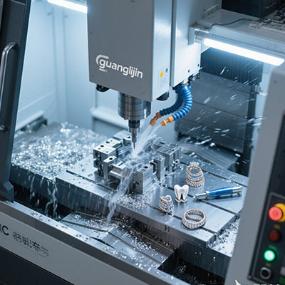
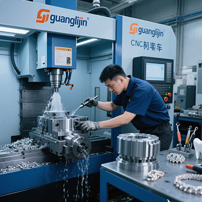
Complex aerospace parts break ordinary machining plans. Twisted blades, deep pockets, compound angles, and thin walls all push against the limits of three-axis equipment. A large 5 axis cnc machine changes the equation by bringing the tool to the feature from any direction. This article covers what makes these machines essential, how to run them, and where shops go wrong.
Why Complex Aerospace Geometry Defeats Three-Axis Setups
Most aerospace components are not boxes. They are organic shapes optimized for weight and aerodynamics. A single impeller may have dozens of curved surfaces meeting at varying angles.
Three-axis machines cannot reach every face without refixturing. Each new setup adds error. Tolerance stacks grow. Lead times stretch. Published research on blisk machining shows domestic five-axis efficiency still trails advanced levels by 30% to 50% . The gap sits in process strategy, not just hardware.
Five-axis simultaneous motion solves the access problem. The tool stays engaged at the optimal angle. Short cutters replace long ones. Deflection drops. Surface quality improves.
Machine Selection: Matching the Platform to the Part Family
Not every large five-axis platform suits every aerospace job. The table below compares two configurations against real production demands.
| Parameter | Project A: Large Gantry Trunnion | Project B: Horizontal High-Speed Mill-Turn |
|---|---|---|
| Max part diameter | 3,000 mm [citation:6] | 1,015 mm [citation:2] |
| Spindle type | HSK/CAT, high torque | Torque table with in-cycle turning [citation:2] |
| Best application | Engine casings, large impellers | Fan seals, ring components |
| Setup reduction | Single setup for multi-face parts | 5 operations compressed to 2 [citation:2] |
| Tolerance capability | Profile accuracy in microns | ±20 µm over full diameter [citation:2] |
Gantry trunnion machines handle massive parts with multi-surface features. Horizontal mill-turn platforms consolidate turning and milling for rotational aerospace components. Match the machine architecture to the dominant part family.
Step-by-Step Process for Complex Part Success
Step 1: Model the full machine kinematics before programming. Import the actual machine model into CAM. Simulate holder, spindle nose, and table clearance. Most crashes on complex parts come from the non-cutting side of the tool assembly.
Step 2: Design fixtures that vanish from the toolpath. Use zero-point clamping with low-profile towers. Position every clamp outside the reach envelope. A fixture collision at hour 15 scraps a part that took a week to rough.
Step 3: Separate roughing and finishing strategies completely. Rough with adaptive trochoidal paths and high radial engagement. Finish with barrel cutters or small stepovers. Shreeram Aerospace cut roughing time 30% with HPC trochoidal milling and gained another 50% on finishing with barrel tools [citation:3].
Step 4: Probe the part between operations. Complex parts move as material leaves. Thermal growth and residual stress both shift geometry. In-process probing catches deviation before the finish pass locks it in.
Step 5: Verify rotary singularity behavior in the post. A C-axis flip at the wrong moment can spin the table violently. Air-cut every new program at reduced feed with the door closed.
Real Shop Floor Experience
Our team tackled an 850 mm parabolic reflector panel on a large bed five-axis center in 2025. The billet started at 150 kg. The finished part weighed 10.5 kg. Wall thickness was 2 mm across the pocket floors.
The first attempt failed on flatness. Fixture deflection during heavy pocketing pushed the walls out of tolerance. We switched to adaptive clearing with reduced radial engagement and added support under the thin sections. Flatness dropped from 28 microns to 9 microns. The drawing required 12.
Shreeram Aerospace reported a parallel result on similar reflector panels. Their process achieved 6-micron precision against a 12-micron tender requirement, while competitors could only reach 70 and 95 microns [citation:3]. The difference came from toolpath strategy and barrel tool finishing, not machine price.
Common Mistakes That Destroy Complex Aerospace Parts
⚠ Attention: Do not clamp on thin finished walls. Clamping force travels through the material and distorts the cut. Use vacuum fixturing or sacrificial tabs instead. A 2 mm titanium wall deflects under minimal jaw pressure.
⚠ Attention: Avoid programming from the CAD model without stock simulation. Complex parts have material where the final geometry will not. The tool path must account for the billet, not the finished shape.
⚠ Attention: Never trust thermal stability on a large machine. A gantry structure can grow 20 to 30 microns in Z during a long roughing cycle. Probe the workpiece between operations and update offsets.
Toolpath and Tooling Choices That Matter
Complex parts reward patience in roughing and aggression in finishing. High-performance roughing removes material fast while keeping heat in the chip. Trochoidal paths maintain constant engagement. Tool life extends. The spindle load stays predictable.
Barrel cutters change finishing economics on curved surfaces. The effective radius is much larger than the physical tool. Stepover increases without scallop height growth. Shreeram reported surface finish improvement from 0.8 µRa to 0.4 µRa on 2 mm pocket walls using this approach [citation:3].
For deep cavities, avoid full slotting. Helical entry with a shallow ramp angle reduces tool pressure at the weakest wall section. The wall survives. The finish pass has material to cut.
FAQ: What Engineers Search Before Committing
Q1: What size part can a large 5 axis cnc machine handle for aerospace work?
Gantry platforms reach 3,000 mm in diameter and 1,950 mm in height [citation:6]. Horizontal mill-turn configurations handle 1,000 mm class rotational parts. Match travel to the largest part family, not the average.
Q2: How tight can tolerances get on complex five-axis aerospace parts?
Published production data shows ±20 µm over a 1,015 mm diameter fan seal [citation:2]. Reflector panels achieved 6-micron profile accuracy across an 850 mm parabolic surface [citation:3]. Success depends on thermal control and probing discipline.
Q3: What is the biggest productivity gain from a large 5 axis cnc machine?
Setup consolidation. Silcoms compressed five operations on three machines into two setups on one Hermle C50 UMT [citation:2]. Floor-to-floor time dropped. Accumulated tolerance error from multiple clamps disappeared.
Q4: Can one large 5 axis cnc machine replace a turning center for aerospace rings?
Yes, with a torque table. In-cycle turning on a five-axis platform handles semi-finish and finish turning in the same setup as milling. Silcoms holds critical features to ±20 µm using this method [citation:2].
Final Checklist Before Cutting Complex Aerospace Parts
- Full machine kinematics simulated with holder and spindle clearance
- Fixture clamps positioned outside the five-axis reach envelope
- Roughing and finishing offsets separated with distinct strategies
- Barrel or high-feed tools selected for curved surface finishing
- In-process probing scheduled for thin-wall and large-span features
- Thermal compensation active with documented soak time
- Post-processor verified for rotary singularity behavior
- Air-cut completed at reduced feed with door closed
- Stock model updated to match actual billet condition
Complex aerospace parts demand more than a capable large 5 axis cnc machine. They demand process discipline. The machine provides access. The strategy provides accuracy. Together, they turn impossible geometry into repeatable production.