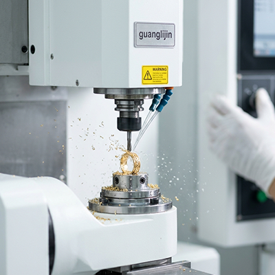
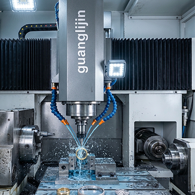
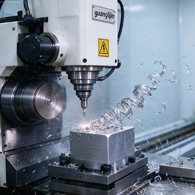
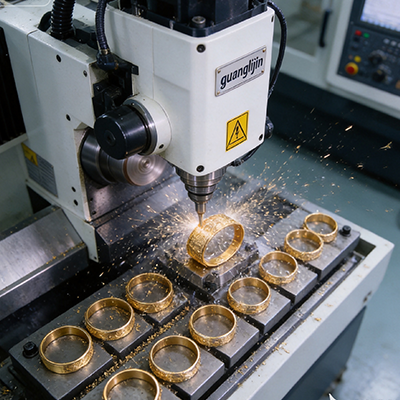
Aerospace parts push every axis to its limit. One feature needs a tight bore. Another needs a sculpted surface. A third needs to be reached from an angle no three-axis machine can touch. A multi axis cnc platform solves the reach problem, but reach alone does not deliver precision. This guide covers the engineering layers that make multi-axis machining work in aerospace.
What Multi-Axis Adds and What It Costs
Every added axis adds capability and error sources. A fourth axis rotates the part or tilts the head. A fifth axis adds a second rotation. The part can reach more orientations, but the machine must track more geometry.
Precision in multi-axis work depends on how well the controller models the rotary axes. RTCP keeps the tool tip on path as those axes move. Kinematic compensation corrects angular positioning error. Without both, the added reach comes with added error.
Aerospace shops see the trade clearly. Multi-axis capability cuts setups and reaches complex geometry. It also demands more from the controller, the CAM software, and the setup routine. The machine is only part of the solution.
Kinematics and Rigidity for Aerospace Cuts
Titanium and Inconel resist cutting. The tool pushes back. That reaction force travels through the spindle and into the machine structure. A rigid platform absorbs it. A flexible one deflects and lets the tool chatter.
Trunnion tables keep the part close to the rotation center. The short lever arm holds rigidity under heavy cuts. Swivel heads move the spindle instead of the part. That suits large parts but adds spindle inertia. Hybrid layouts split the motion and add programming complexity.
Guideway choice matters too. Box ways damp vibration through large contact area. Linear guides offer speed and less damping. Aerospace structural parts often favor the damping.
Research on five-axis machine tools shows that geometric and thermal errors dominate part error when the machine is rigid enough for the cut. Work published in CIRP Annals reports that thermal errors account for 40–70% of total machining error on precision machine tools. Rigidity alone does not solve the problem.
Comparing Two Multi-Axis Aerospace Setups: Project A vs. Project B
| Parameter | Project A: Trunnion + Full Compensation | Project B: Swivel Head + Basic RTCP |
|---|---|---|
| Part type | Ti-6Al-4V structural bracket | Ti-6Al-4V structural bracket |
| Kinematics | Trunnion table, A and C axes | Swivel head, B and C axes |
| Controller compensation | RTCP plus kinematic compensation | RTCP basic |
| Thermal strategy | Ballscrew cooling, pivot temperature compensation | Warm-up only |
| Angled feature error | ±0.012 mm | ±0.035 mm |
| Surface finish on wall | Ra 0.6 µm | Ra 1.0 µm |
| Tool life per edge | 30 parts | 21 parts |
Project A invested in kinematic compensation and thermal control. That investment showed up in angled feature accuracy and tool life. Project B relied on basic RTCP and warm-up alone. The gap on angled features was nearly 3:1. Precision multi-axis work is a system, not just an axis count.
Error Mapping Across Multiple Axes
Each axis carries its own error signature. Linear axes show positioning, straightness, and squareness errors. Rotary axes show angular positioning and backlash. When the axes work together, those errors combine in complex ways.
Volumetric error mapping measures the combined error across the working volume. A laser tracker or ballbar captures the data. The controller’s compensation tables correct for it. ISO 230-1 defines the geometric error measurement procedures that underlie this work.
Our team mapped a multi-axis machine in 2025 for a titanium bracket program. The combined error at the far corner of the work volume reached 41 µm before compensation. After volumetric mapping and compensation, it dropped to 14 µm. The machine’s individual axes had looked acceptable. The combination had not.
Rotary axis mapping is a separate task. Angular positioning error, radial motion error, and backlash each need measurement. A rotary encoder check alone misses mechanical errors in the table or head structure.
Step-by-Step: Multi-Axis Error Mapping Workflow
- Warm the machine. Run a full warm-up cycle for at least two hours before mapping. Map in the working thermal state.
- Measure linear axis errors. Use a laser interferometer for positioning, straightness, and squareness on X, Y, and Z.
- Measure rotary axis errors. Capture angular positioning and backlash on each rotary axis with an indexing table or encoder.
- Build the combined error model. Combine all measured parameters into a kinematic error model using the controller’s mapping tool.
- Apply compensation tables. Load the corrections into the controller and verify with a test cut at multiple locations.
- Re-map every six months. Wear and thermal cycles shift the error map. Re-mapping catches drift before it reaches parts.
Thermal Control on a Multi-Axis Platform
Multi-axis machines generate heat in more places than three-axis machines. Rotary axes have their own drives and bearings. The spindle head sits near the cutting zone on a swivel machine. The trunnion motor sits under the part on a table machine.
Thermal growth moves the pivot point. When the pivot moves, RTCP compensates against a wrong reference. The tool tip drifts even though the controller reports no fault. This error is hard to see and harder to diagnose.
Pivot temperature compensation addresses it. Temperature sensors on the rotary axes feed the controller. The controller adjusts the pivot model as the temperature changes. Ballscrew cooling handles the linear drift separately.
The multi axis cnc platform in aerospace work rewards shops that control all the error sources. Kinematics, compensation, mapping, and thermal control work together. Skip one and the others carry more burden than they can handle.
Frequently Asked Questions
What is the difference between multi axis CNC and 5-axis CNC machining?
Multi axis CNC refers to machines with four or more axes. Five-axis CNC is the most common precision configuration, with two rotary axes plus three linear axes. Some machines offer more than five axes for specialized work.
Why does aerospace machining need multi axis CNC capability?
Aerospace parts carry complex geometry, angled features, and tight tolerances. Multi-axis machining reaches those features in one setup. That reduces setup error and improves accuracy on sculpted surfaces.
What is volumetric error compensation on a multi axis CNC machine?
Volumetric error compensation measures combined errors across the working volume and corrects them in the controller. It addresses the interaction between linear and rotary axes that individual axis tests miss.
How does thermal drift affect multi axis CNC accuracy?
Thermal growth moves the rotary pivot point. RTCP then compensates against a wrong reference, and the tool tip drifts without any fault code. Pivot temperature compensation and ballscrew cooling reduce this error.
How often should a multi axis CNC machine be re-mapped?
Re-map every six to twelve months, and after any crash or rotary axis repair. High-precision aerospace shops re-map more often because thermal cycling and wear shift the error model.
Multi-Axis Aerospace Machining Checklist
- Confirm RTCP and kinematic compensation are active.
- Verify the machine is warm before precision cuts or mapping.
- Measure linear axis positioning, straightness, and squareness.
- Measure rotary axis angular positioning and backlash.
- Apply volumetric compensation tables in the controller.
- Map pivot temperature and enable thermal compensation.
- Cut a combined test part that exercises all axes together.
- Measure the test part on a CMM against the drawing.
- Re-check accuracy after four hours of continuous running.
- Schedule re-mapping every six months or after any crash.