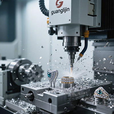
Aerospace buyers rarely order standard parts. Every bracket, housing, and blade carries a custom drawing with tight tolerances and awkward geometry. That is where cnc milling 5 axis earns its place. It lets a shop cut complex aerospace parts in fewer setups, with better surface control and less re-fixturing error.
This guide covers the practical side. What makes custom aerospace parts hard? How does five-axis work change the outcome? And what should you check before you release a program to the floor?
Why Custom Aerospace Parts Resist Simple Machining
Custom means the geometry was designed for function, not for easy machining. A fuel manifold may have ports at compound angles. A structural rib may carry tapered walls and curved flanges. A sensor housing may need deep pockets with thin floors.
Three-axis milling handles flat faces and straight walls well. Angled ports and curved flanges force extra setups. Each setup adds a datum shift. On a part with position tolerances between features, those shifts stack up.
Five-axis machining solves the access problem. The spindle tilts and the table rotates. The tool reaches angled faces without unclamping the part. The datum stays intact. Feature relationships stay tight.
What Changes When the Part Is Custom
Custom aerospace work is not a repeat production run. Every job brings a new model, a new fixture, and a new set of risks. The shop must plan from scratch more often. Programming time grows. Simulation becomes essential, not optional.
We felt this in our own shop last year. A customer sent a custom titanium housing with six angled ports and a thin mounting flange. The first three-axis plan required five setups and a custom angle plate. We switched to a five-axis plan with two setups. The flange stayed flat. The ports hit position on the first article.
That result is not automatic. It came from careful datum planning and full machine simulation before the first cut. Custom work rewards preparation and punishes shortcuts.
Comparing Two Custom Aerospace Projects
The table below contrasts two custom jobs. Both are low-volume, high-mix work. The machining priorities differ sharply.
| Project Parameter | Project A: Custom Aluminum Manifold | Project B: Custom Inconel Nozzle Ring |
|---|---|---|
| Part count | 12 pieces | 4 pieces |
| Key challenge | Compound-angle ports, thin flange | Heat, tool wear, deep curved slots |
| Setup count (3-axis plan) | 5 setups | 7 setups |
| 5-axis strategy | 3+2 positional for ports | Simultaneous motion for slots |
| Typical tolerance | ±0.025 mm on port position | ±0.015 mm on slot profile |
| Main risk | Flange distortion from clamping | Tool wear and surface hardening |
| Tooling focus | Sharp carbide end mills, high helix | Coated ball nose, through-coolant |
| Inspection method | CMM with port-axis alignment | Profile scan plus CMM checkpoints |
The aluminum manifold is an access problem. Positional five-axis work removes three setups and protects the flange. The Inconel ring is a thermal and wear problem. Simultaneous motion keeps the cutter engaged at a stable angle, but the tooling and coolant strategy carry the job.
Step-by-Step Guide: Planning a Custom Five-Axis Aerospace Job
Good planning beats a bigger machine. Follow these steps before the first chip flies.
Step 1: Map Every Feature to an Axis Strategy
List each feature on the drawing. Mark whether it needs three-axis, positional five-axis, or simultaneous five-axis access. This map drives the setup plan. It also exposes features that could be combined into one operation.
Step 2: Choose Datums That Survive the Whole Job
Custom parts often have no natural datum. Pick a primary face and two locating features that stay accessible. If the datum is buried after roughing, you lose your reference for finishing. Plan the sequence so critical datums are cut early or protected.
Step 3: Design the Fixture Around the Part, Not the Table
Thin flanges and curved walls distort under clamping force. Use custom soft jaws or a conformal fixture. Support the part under the cut zone. Minimize clamp pressure. A rigid fixture with light force beats a heavy clamp every time.
Step 4: Simulate with the Real Tool Holder and Fixture
Five-axis motion paths are not intuitive. Load the actual holder model. Check clearance on every tilted approach. Check table-to-spindle distance on deep pockets. A crash in simulation costs minutes. A crash on the machine costs days.
Step 5: Cut a First Article and Measure Before Proceeding
Custom parts have no history. Cut one piece. Measure all critical features. Compare the results to the model. Adjust the program if needed. Lock the program only after the first article passes.
⚠ Attention: Common Mistakes in Custom Five-Axis Aerospace Work
Mistake 1: Treating a custom part like a production part. Production programs are proven. Custom programs are untested. Budget extra time for simulation and first-article checks.
Mistake 2: Ignoring rotary axis error on long parts. A small rotary error grows with distance from the center of rotation. On long aerospace parts, check rotary calibration before the job.
Mistake 3: Over-clamping thin custom features. Five-axis access does not fix a distorted part. Light clamping force and conformal support are essential on thin flanges and walls.
Mistake 4: Skipping the stock model check. Custom castings and forgings vary. Check the actual stock envelope before programming. A program built on nominal stock may cut air or crash.
Material Behavior and Process Control
Custom aerospace parts span aluminum, titanium, and nickel alloys. Each behaves differently under the cutter. Aluminum cuts fast and hot. Titanium work-hardens if the tool rubs. Nickel alloys wear tools quickly and hold heat at the edge.
Published machining data for Inconel 718 shows that cutting speeds above roughly 40 to 50 surface meters per minute with carbide tools accelerate flank wear sharply. The practical response is lower speed, higher feed per tooth, and coolant directed at the flank. Five-axis tool orientation supports this by keeping the engagement angle stable.
For titanium, high-pressure coolant through the spindle is more effective than flood coolant on deep cavities. The pressure clears chips and cools the edge. On thin walls, a tilted ball nose cutter spreads the cutting force and reduces deflection.
Therefore, the process plan must match the alloy. A program that works on aluminum will fail on Inconel. The machine does not change the metallurgy.
How Custom Work Differs from Production Work
Production work rewards cycle time. Custom work rewards first-article success. The priorities invert.
On a production job, the program is stable and the setup is fixed. On a custom job, the program is new and the setup is built from scratch. Simulation, fixture design, and inspection planning take a larger share of the total effort.
Custom shops that succeed with five-axis work build a repeatable planning process. They do not rely on operator skill alone. They use checklists, simulation, and first-article measurement as standard steps.
Frequently Asked Questions
Can 5-axis CNC milling handle custom aerospace parts with tight tolerances?
Yes, for well-supported features. Typical achievable tolerances run from ±0.005 mm to ±0.02 mm depending on material and geometry. Thin walls and deep cavities widen the range. Fixturing and toolpath strategy often matter more than the machine specification.
What is the difference between 3+2 and simultaneous 5-axis for custom aerospace work?
3+2 positions the part at a fixed angle and cuts with three axes. It suits angled holes and flat faces. Simultaneous five-axis moves all axes together. It suits twisted blades, curved slots, and continuous contours. Most custom jobs use both strategies.
How many setups can five-axis machining eliminate on a custom aerospace part?
It depends on the geometry. A part with angled ports on four faces may drop from five setups to two. A complex housing with curved cavities may drop from seven to three. The savings come from reaching multiple faces without re-fixturing.
What materials are hardest to machine for custom aerospace parts?
Nickel-based superalloys and titanium alloys are the most demanding. They generate high heat, wear tools quickly, and can deflect thin sections. Proper tool selection and coolant delivery are critical.
How do I choose a machine style for custom five-axis aerospace milling?
Trunnion machines suit smaller, denser parts with good access. Gantry machines handle long structural parts. The choice depends on part size, weight, and spindle reach. Custom work benefits from a machine with easy fixture access and good simulation support.
Final Checklist: Before You Cut a Custom Aerospace Part
- ☐ Feature map completed with axis strategy for each face
- ☐ Datum plan verified against drawing and assembly requirements
- ☐ Fixture designed for light clamping and full support
- ☐ Actual stock envelope measured and loaded into CAM
- ☐ Full machine simulation run with real holder and fixture
- ☐ Rotary axes calibrated and verified
- ☐ Coolant pressure and direction matched to the alloy
- ☐ First-article inspection plan includes all critical features
- ☐ Program locked with revision number after first-article pass
- ☐ Operator briefed on clearance risks and clamping limits
Custom aerospace work is a planning discipline. The machine provides the reach. The process provides the precision. Shops that combine both deliver parts that pass inspection the first time. For teams building that capability, cnc milling 5 axis is the platform that makes complex custom geometry practical, repeatable, and inspection-ready.