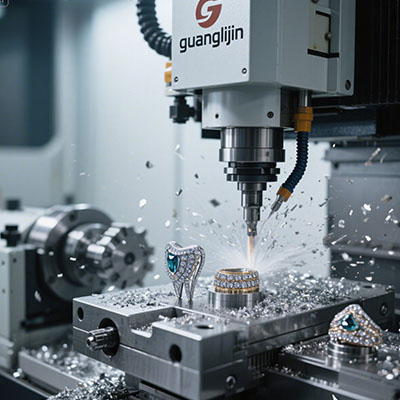
Aerospace parts are not forgiving. A blade root that is off by a few microns can fail inspection. A housing with mismatched hole positions may not assemble on the engine. This is why cnc milling 5 axis has become the standard route for critical components. It is not about having more axes for the sake of it. It is about reaching features in one setup that would otherwise require five.
Why Aerospace Machining Pushes Toward Five Axes
Conventional three-axis milling works well for prismatic parts with features on one face. Aerospace geometry rarely cooperates. Blades twist. Housings have deep cavities and angled ports. Brackets carry compound curves and thin walls.
Each additional setup introduces error. The part comes off the fixture, gets re-clamped, and the datum shifts. Five-axis machining reduces this risk by allowing the tool to approach the workpiece from multiple directions without re-fixturing[citation:3]. The spindle tilts, the table rotates, and the same setup covers five faces.
We saw this directly in our shop. A titanium bracket used to require four separate operations across two machines. After moving the job to a simultaneous five-axis setup, the cycle dropped to one operation. Setup time fell by more than half. The scrap rate on the first article went to zero.
The Real Challenges: Heat, Chatter, and Thin Walls
Titanium and nickel-based alloys dominate aerospace work. These materials hold strength at high temperatures, which is great for the engine and terrible for the cutter. Heat concentrates at the cutting edge. Tool wear accelerates. Dimensional drift follows.
Five-axis motion helps by keeping the tool engaged at a consistent angle. A ball nose cutter can be tilted to use the side of the tool rather than the tip. This spreads the wear and improves surface finish. The same tilt reduces chatter on thin walls by changing the contact geometry.
According to published process benchmarks, five-axis machining can hold tolerances in the range of ±0.0004 to ±0.001 inches on well-supported features, with surface finishes between Ra 0.4 and Ra 1.6 micrometers[citation:8]. These numbers assume the setup is rigid and the toolpath is stable. On thin-walled blades, the achievable range widens.
Comparing Two Aerospace Projects: A Side-by-Side View
The table below contrasts two typical aerospace jobs. One is a structural bracket with moderate complexity. The other is a thin-walled impeller with deep flow channels. Both benefit from five-axis work, but the priorities differ.
| Project Parameter | Project A: Titanium Bracket | Project B: Nickel Alloy Impeller |
|---|---|---|
| Primary challenge | Angled holes and compound faces | Thin walls and deep channels |
| Setup count (3-axis estimate) | 4 setups | 6+ setups |
| 5-axis strategy | 3+2 positional for angled features | Simultaneous five-axis for flow paths |
| Material removal concern | Moderate | High (over 90% removal) |
| Typical tolerance target | ±0.02 mm | ±0.015 mm on blade profile |
| Key risk | Hole position drift from re-fixturing | Deflection and chatter on thin blades |
| Tooling emphasis | Rigid end mills, indexable cutters | Ball nose with variable helix, small stepover |
The bracket case is simpler. Positional five-axis work eliminates three setups. The impeller demands simultaneous motion because the channel twists while the blade thins. Different problems, same machine platform.
A Step-by-Step Guide to Planning a Five-Axis Aerospace Job
Planning matters more than the machine specification. A well-planned three-axis job can beat a poorly planned five-axis job. Follow these steps for aerospace work.
Step 1: Analyze the Model for Five-Axis Value
Not every feature needs five-axis motion. Identify which faces require angled access. Determine whether positional (3+2) work can handle the part. Reserve simultaneous motion for the features that truly need it. This reduces programming time and lowers crash risk.
Step 2: Define the Datum Strategy Before Programming
Choose a primary datum that remains accessible throughout the operation. For aerospace parts, the datum often relates to the assembly interface. If the datum is buried after the first operation, you lose your reference. Plan the machining sequence so that critical datums are cut last or remain exposed.
Step 3: Select Tooling for the Material, Not the Machine
Titanium wants sharp edges and high pressure coolant. Nickel alloys want rigid tools with heat-resistant coatings. Aluminum aerospace parts want polished flutes and high helix angles for chip evacuation. The five-axis capability does not change the metallurgy. Use the tool that matches the alloy.
Step 4: Simulate with Collision Checking Enabled
Five-axis crashes are expensive. The rotary axes introduce motion paths that are not always intuitive. Run full machine simulation with the actual tool holder and fixture model. Check for holder-to-part clearance on tilted approaches. Check for table-to-spindle interference on deep cavities.
Step 5: Lock Proven Programs Before Production
Once a program passes first article inspection, lock the operations. Changes to feeds or speeds in one operation can shift the toolpath in another. Version control prevents accidental edits that pass simulation but fail on the floor.
⚠ Attention: Common Five-Axis Mistakes in Aerospace Work
Mistake 1: Using five-axis for everything. Positional work on a three-axis machine is often faster and simpler. Five-axis programming takes longer and introduces rotary errors. Use it where it solves a real problem.
Mistake 2: Ignoring the rotary axis accuracy. The linear axes may be perfect. The rotary axes may have backlash or thermal drift. On long aerospace parts, rotary error multiplies at the tool tip. Check rotary calibration before critical jobs.
Mistake 3: Over-clamping thin walls. Five-axis access does not fix a distorted part. Excessive clamping force on a thin blade or housing wall creates spring-back after unclamping. Use custom fixtures and minimum force.
Materials and Process Control: What Actually Moves the Needle
Nickel-based superalloys like Inconel 718 are common in engine components. They work-harden quickly. If the tool rubs instead of cuts, the surface hardens and the next pass wears the cutter rapidly. Five-axis tool orientation helps keep the chip load consistent, but the cutting parameters must be aggressive enough to cut below the hardened layer.
Titanium alloys such as Ti-6Al-4V have low thermal conductivity. Heat stays at the edge. High-pressure coolant directed at the flank is more effective than flood coolant. Through-spindle coolant helps further on deep cavities.
For thin-walled aerospace parts, the machining strategy matters as much as the machine. Roughing removes bulk material. Semi-finishing establishes uniform stock. Finishing takes light passes with a tilted tool to reduce radial force. A staged approach with stress-relief between roughing and finishing improves dimensional stability[citation:3].
Frequently Asked Questions
What tolerances can 5-axis CNC milling hold for aerospace parts?
Well-supported features can reach ±0.005 mm to ±0.02 mm depending on material, geometry, and machine condition. Thin walls and deep cavities widen the achievable range. The machine is only one variable; fixturing and toolpath strategy often determine the final result.
How does simultaneous 5-axis differ from 3+2 machining for aerospace work?
3+2 machining positions the part at a fixed angle and cuts with three axes. It is faster to program and stable for angled holes and faces. Simultaneous five-axis moves all axes together, which is necessary for twisted blades and continuous contours. Most aerospace jobs use both strategies on the same part.
Why is five-axis milling preferred over multiple three-axis setups for complex aerospace components?
Each setup introduces a new datum and a new opportunity for error. On a part with tight position tolerances between features, re-fixturing stacks up variation. Five-axis machining completes more features in one setup, preserving the relationship between surfaces.
What materials are hardest to machine with 5-axis CNC in aerospace?
Nickel-based superalloys and titanium alloys are the most demanding. They generate high cutting heat, wear tools quickly, and can deflect thin sections. Proper tool selection, coolant delivery, and toolpath strategy are critical for these materials.
How do I choose between a trunnion-style and a gantry-style 5-axis machine for aerospace parts?
Trunnion machines handle smaller, denser parts with good accessibility. Gantry machines accommodate long structural components like wing ribs and fuselage sections. The choice depends on part size, weight, and the required reach of the spindle.
Checklist: Before You Release the Program
- ☐ Datum scheme verified against the drawing and assembly requirements
- ☐ Tool holder and fixture models loaded into simulation
- ☐ Rotary axis calibration checked within the last 30 days
- ☐ Coolant pressure and direction confirmed for the material
- ☐ First article inspection plan includes all critical features
- ☐ Program locked and backed up with revision number
- ☐ Operator briefed on any tilted approaches or clearance risks
- ☐ Stress-relief or intermediate inspection scheduled for thin-wall parts