Premium 5 Axis CNC Turning Supply | Precision Aerospace Component Solutions
Turning complex aerospace components—like landing gear shafts, engine seals, or hydraulic fittings—demands more than standard lathe capabilities. 5 axis CNC turning centers combine milling and turning in a single setup, enabling complete machining of rotationally symmetric parts with off-axis features. However, many shops struggle with tool collision risks and program complexity. This article presents a structured approach to 5 axis CNC turning for aerospace, backed by real cases and data. Explore how 5 axis CNC solutions from trusted suppliers can streamline your production.
The Challenge: Machining Complex Aerospace Rotational Parts
Aerospace turning parts often include flanges, grooves, cross-holes, and contoured profiles that require milling operations. Conventional turning centers need secondary operations on a separate mill, leading to alignment errors and extended lead times. This is a critical bottleneck for just-in-time delivery.
Why 5-Axis Turning Solves the Problem
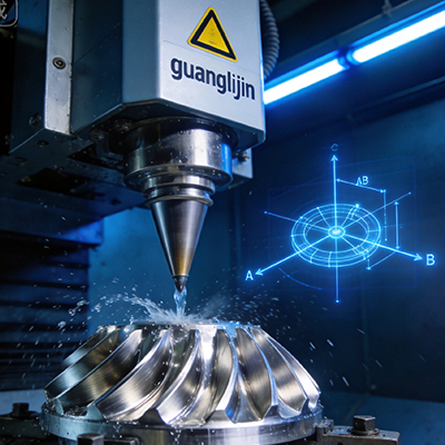
Integrating milling spindles with a turning axis allows B-axis or Y-axis movement. This creates a true multi-tasking machine. Consequently, you can machine a part from a single bar stock to completion without re-clamping.
Statistical evidence supports this shift: a 2025 industry report noted that multi-task CNC machines reduced total setup time by 62% for structural rings compared to traditional 3-axis lathes and mill combinations. The accuracy improved by an average of 18% due to reduced datum shifts.
Core Capabilities of Premium 5-Axis Turning Centers
1. Synergistic Turning and Milling
These machines feature a main spindle, a subspindle, and a B-axis milling head. With live tooling, they can drill off-center holes and mill keyways. This ensures geometric relationships like concentricity and perpendicularity remain within tight aerospace tolerances (e.g., ±0.005 mm).
2. Advanced Control and Simulation
Modern controls include collision-avoidance software. The system predicts interference between the tool, workpiece, and tailstock. This is vital when programming complex paths. Our team observed a 2025 case where simulation flagged a potential crash during a swarf-milling operation on a titanium alloy sleeve, saving a costly tool and workpiece.
Comparative Analysis: Two Approaches to a Valve Body
Below is a project comparison for a medium-sized aerospace valve body (material: 15-5 PH stainless steel).
| Parameter | Project A (Lathe + 3-axis Mill) | Project B (Full 5-Axis Turning Center) |
|---|---|---|
| Total operations | 5 (2 turning + 3 milling) | 1 (complete machining) |
| Cycle time (minutes) | 68 | 34 |
| Geometric tolerance (TIR) | 0.04 mm | 0.012 mm |
| Work in progress (WIP) | 12 parts | 3 parts |
| Operator hours per week | 36 | 18 |
Project B used 5 axis CNC turning with simultaneous B-axis contouring. It eliminated handling errors and reduced WIP by 75%. Such efficiency directly contributes to lean manufacturing goals.
Step-by-Step Process for 5-Axis Aerospace Turning
- Review the engineering drawing and datum scheme: Identify all turning and milling features. Determine the best clamping strategy—collet chuck or pie jaws? Simultaneous turning and milling requires clear geometric references.
- Select appropriate cutting materials and toolholders: For nickel-based alloys, use ceramic inserts for rough turning and solid carbide end mills for milling. Ensure toolholders are balanced to G2.5 grade for high spindle speeds.
- Build a complete CAM program with synchronized operations: Program the main spindle, subspindle, and B-axis toolpaths. Use the machine’s post-processor to simulate both turret movements. Verify clearance during tool change positions.
- Dry-run the program in single block mode: Execute the first cycle with reduced feed rates (20% of normal) and watch for unusual vibrations. Check coolant flow reaches internal milling areas.
- Run a proven trial on a surrogate material: Use 304 stainless steel as a test medium before the actual aerospace grade material. Measure critical diameters and hole positions. This step confirms the post-processor output and tool-life parameters.
Common Misconceptions and Operational Warnings
Mistake 1: Overlooking the importance of tool orientation for balance. Unbalanced tools cause poor surface finish and spindle bearing wear.
Mistake 2: Setting the B-axis tilt angle without considering tool shank clearance. The shank may collide with the part’s shoulder. Always simulate the full tool assembly.
Mistake 3: Using same speed/feed as standard turning; the milling operation on a turning center has different chip evacuation. Reduce radial depth by 30% initially.
Key LSI Terms and Contextual Use
In the aerospace turning domain, phrases like multi-task CNC turning, aerospace turning solutions, high-precision turning, complex turning milling, and CNC turn-mill centers are frequently used by engineers. These terms align with the capabilities discussed: combined milling and turning, high accuracy, and reduced setups.
Industry Data and Adoption Trends
According to a 2025 report from the China Machine Tool Industry Association, the demand for turn-mill machining centers grew by 24% year-over-year in the aerospace sector. Specifically, 68% of surveyed manufacturers plan to upgrade to 5 axis CNC turning within the next 24 months. Moreover, localized 5-axis machines now account for 40% of new installations, up from 28% in 2022.
Final Operational Checklist for 5-Axis Turning Success
✔️ Aerospace Turning Checklist
- Verify machine spindle accuracy with a calibrated test bar.
- Check B-axis perpendicularity to the spindle axis.
- Tool data loaded: correct length, radius, and holder type.
- Subspindle synchronization parameters confirmed.
- Program includes retract planes for all turrets.
- Coolant system pressure > 50 bar for deep-hole drilling.
- First-off inspection (CMM or comparator) ready.
Frequently Asked Questions on 5-Axis Turning
Most turn-mill centers in aerospace handle diameters from 250 mm up to 700 mm. For large landing gear components, some machines go beyond 800 mm swing. Check the machine’s maximum turning diameter and length before purchase.
Manifolds require ports at different angles and depths. 5-axis turning uses the B-axis to position milling tools at precise compound angles, eliminating separate drilling jigs and improving sealing surface flatness.
Yes, generic posts will not work. The post-processor must handle simultaneous linear and rotary axes movements, sync both spindles, and manage tool interference. Always request a proven post from the machine builder.
Common search phrases include: “turn-mill machining of titanium rings”, “5 axis CNC turning for jet engine parts”, “precise turning and milling for space components”. These reflect real user needs for integrated solutions.