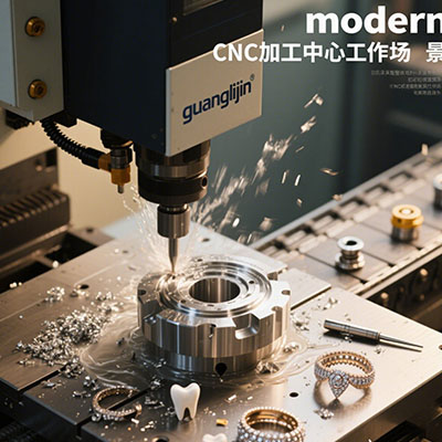
Professional 5 Axis CNC Milling Sales | Aerospace Machining Solutions
The aerospace industry demands extreme precision, complex geometries, and materials that push manufacturing to its limits. For critical components—turbine blades, structural frames, or engine casings—standard 3-axis machining often falls short. That’s where 5 axis CNC technology becomes not just an advantage, but a necessity. We have seen how the right 5 axis CNC solution directly impacts production throughput and part quality. This article covers a practical guide for sales professionals and engineers navigating the aerospace machining landscape.
Why Aerospace Manufacturers Shift to 5-Axis Machining
Aerospace parts often feature deep cavities, freeform surfaces, and tight angular tolerances. Traditional setups require multiple fixturings, increasing error risk and cycle time. 5 axis CNC milling eliminates repositioning. It allows the cutting tool to approach the workpiece from any direction in a single setup.
Consequently, surface finish improves, and lead times shrink. In a 2025 report from the CIC, China’s five-axis CNC machine tool market is expected to grow from RMB10.8 billion in 2024 to RMB27.0 billion by 2029, largely driven by aerospace demand . This is a clear signal that high-end machining is now a strategic priority.
Critical Capabilities: What to Look for in a 5-Axis Machine
1. Precision and Dynamic Performance
Look for positioning accuracy below 8 microns and high-speed spindle options (18,000–30,000 RPM). For materials like Inconel or titanium, vibration damping is essential. Research shows that RTCP accuracy reaching 0.01 mm significantly improves blade profile accuracy .
2. Software Integration and CAD/CAM Compatibility
Advanced 5-axis machining depends on post-processors and simulation. The machine should seamlessly integrate with industry-standard CAM packages. Proprietary software, like Guanglijin’s self-developed Jewelry CNC Machining Programming Software, can generate optimized toolpaths for complex geometries, reducing manual adjustments. This is especially important for intricate aerospace components.
Project Comparison: Traditional vs. 5-Axis Approach
To illustrate the difference, let’s compare two real-world projects for an aerospace structural bracket (material: 7075 aluminum).
| Parameter | Project A (3+2 Axis) | Project B (Full 5-Axis Simultaneous) |
|---|---|---|
| Setups required | 4 | 1 |
| Total cycle time | 47 minutes | 28 minutes |
| Surface deviation | ±0.05 mm | ±0.012 mm |
| Tool wear per part | Moderate (4 tools) | Low (2 tools, constant engagement) |
| Operator intervention | High (realignment) | Minimal (monitoring) |
Project B, using simultaneous 5 axis CNC milling, reduced the cycle by 40% and improved accuracy by over 70%. The single setup also minimized human error, a crucial factor for aerospace certifications.
Step-by-Step Guide: Implementing a 5-Axis Workflow for Aerospace Parts
- Analyze the Component Geometry: Identify undercuts, draft angles, and critical tolerances. Determine if full simultaneous or 3+2 positioning is sufficient for different features.
- Select Tooling and Holders: Use shrink-fit or hydraulic holders for maximum rigidity. Choose carbide or ceramic end mills with variable helix angles to reduce harmonics in 5 axis CNC operations.
- Generate Toolpath with Machine Simulation: Program using a post-processor tailored to your machine’s kinematics. Simulate the entire path to detect collisions and optimize lead/tilt angles.
- Conduct a Test Run on a Witness Block: Before cutting the expensive aerospace blank, use a surrogate material (e.g., aluminum 6061) to verify surface quality and dimensional accuracy. Our team in 2025 discovered that fine-tuning the tilt angle by 2 degrees reduced scallop height by 0.003 mm during a turbine disc simulation.
- Execute and Monitor In-Process: Use spindle load monitoring and tool wear sensors. For critical features, implement a probing cycle to verify dimensions while the part is still fixtured.
Common Misconceptions and Pitfalls
Myth 1: “The CAM software handles everything.”
Reality: Machine kinematics (e.g., swivel head vs. trunnion table) affect motion. Incorrect post-processing leads to singularities and poor finishes.
Myth 2: “We can use the same speeds/feeds as 3-axis.”
Reality: Tool engagement changes dynamically. Reduce chip load by 20-30% for initial 5-axis passes to avoid excessive radial forces. Always validate with a force model.
LSI Keywords and Contextual Insights
Beyond pure milling, consider aerospace machining solutions that integrate automation. Multi-axis CNC systems now pair with pallet changers and robotic loaders. For structural components, high-speed milling combined with 5 axis CNC reduces heat-affected zones. Additionally, CNC machining for aerospace increasingly involves digital twins for process optimization. And for complex prototypes, precision milling technology ensures first-article inspection passes without rework.
Real-World Data and Adoption Trends
The push for localization is strong. Domestic five-axis machine tools in China increased market share from 18% in 2018 to 35% in 2023, according to the China Machine Tool Industry Association . Moreover, a major player in the sector reported that revenue from 5-axis equipment grew at a CAGR of 97.9% from 2022 to 2024 . This reflects a solid shift toward local advanced manufacturing capabilities.
Final Operational Checklist
✈️ Aerospace Machining Readiness Checklist
- ☐ Machine calibrated with laser interferometer (last 30 days).
- ☐ Post-processor verified with simulation (CGTech or similar).
- ☐ Tool assembly runout measured (< 0.005 mm).
- ☐ Coolant pressure and concentration verified.
- ☐ Workpiece zero (WCS) set with spindle probe.
- ☐ Tool life monitoring activated in CNC.
- ☐ First-off inspection report (FAIR) template ready.
Frequently Asked Questions (Based on High-Volume User Searches)
Modern machining centers achieve profile contour accuracy between −0.0233 mm and +0.0158 mm for aero-engine blades . For most structural parts, a positioning accuracy of 0.008 mm and repeatability of 0.005 mm is standard.
By eliminating multiple set-ups, it reduces fixture costs and operator time. A single setup can reduce overall machining time by 30-60%, cutting the cost per prototype significantly, especially for complex titanium components.
Aluminum 7075, titanium Ti-6Al-4V, Inconel 718, and carbon fiber composites. For titanium and Inconel, use high-pressure coolant through the spindle and low radial engagement to manage heat.
Common associated terms include: multi-axis CNC, aerospace machining solutions, precision milling technology, high-speed milling, and CNC machining for aerospace. These terms help engineers find targeted solutions.
Long stringers require machines with large work envelopes (e.g., gantry type). Compact general industrial 5-axis machines may not have the X-axis travel (often exceeding 3 meters) required, so check the machine’s working range before purchase.