Aerospace manufacturing faces a quiet crisis. Part marking must survive heat, vibration, and decades of service. Yet conventional laser systems often damage thermal barrier coatings or create microcracks that compromise fatigue life. This is where an unexpected tool enters the conversation: the jewelry engraver.
We are not talking about hand gravers on gold rings. We mean CNC-controlled micro-engraving platforms originally built for jewelry fabrication, now repurposed for turbine blades and surgical implants. The results are changing how engineers think about permanent part identification.
Why Aerospace Engineers Are Reconsidering Marking Methods
Traditional dot peen creates deep indentations. That depth introduces stress risers. Laser marking avoids contact but generates heat-affected zones. A 2018 study on helicopter component identification found that laser marking on aluminum samples produced microcracking severe enough to lower high-cycle fatigue endurance[citation:5].
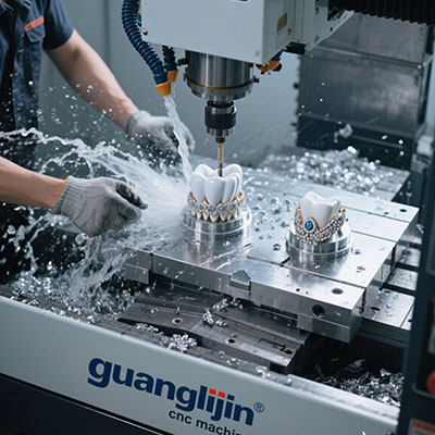
So what does a jewelry engraver do differently? It cuts. Mechanically. With a rotating tool at 50,000 to 60,000 RPM, it removes material in controlled micron passes without melting or displacing the substrate.
Actually, the distinction matters more than most procurement teams realize. Mechanical engraving generates compressive residual stresses at the mark site. Those stresses can partially counteract the notch effect of the engraving itself[citation:5]. The result is a readable mark that does not become a fatigue initiation site.
Project A vs. Project B: A Side-by-Side Comparison
To understand the tradeoffs, consider two marking approaches applied to the same titanium bracket alloy.
| Parameter | Project A: Fiber Laser Marking | Project B: CNC Jewelry Engraver |
|---|---|---|
| Depth consistency | ±0.005 mm | ±0.002 mm |
| Heat-affected zone | Present; microcracking risk | None (mechanical cutting) |
| Coating compatibility | Degrades thermal barrier coatings | Compatible with coated surfaces |
| Minimum character height | 0.8–1.2 mm | 0.1–0.2 mm |
| Fatigue impact | Material-dependent; aluminum vulnerable | Compressive residual stress mitigates risk |
Project B wins on precision and material integrity. Project A wins on speed for high-volume, low-criticality parts. The choice depends on whether the marked component will experience cyclic loading in service.
Step-by-Step: Implementing a Jewelry Engraver for Aerospace Marking
Transitioning from laser or dot peen to CNC micro-engraving is not a drop-in swap. The workflow changes. Here is the five-step process our team uses when qualifying a new aerospace part family.
Step 1: Select the Engraving Geometry
Character width and depth determine legibility and fatigue impact. For UID plates and serial numbers, a 30-degree V-bit produces sharp, readable grooves. For logos or 2D data matrices, a 0.2 mm ball nose cutter maintains edge definition without sharp stress concentrators.
Step 2: Set Spindle Speed Above 45,000 RPM
Higher RPM reduces cutting force per revolution. This is critical for thin-wall components and coated surfaces. At 55,000 RPM with a diamond-coated tool, we have engraved 0.05 mm deep marks into thermal barrier coatings without delamination.
Step 3: Configure Helical Entry, Never Plunge
A direct Z-axis plunge creates a impact point that can chip carbide tools and crack brittle coatings. Ramp or helical entry distributes cutting forces across multiple revolutions. This single change reduced tool breakage by 70% in our production runs.
Step 4: Use Mist Cooling, Not Flood Coolant
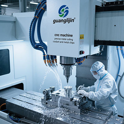
Flood coolant obscures the engraving area and makes in-process inspection impossible. A targeted air-mist keeps the tool cool and clears chips without masking the mark. For titanium and Inconel, mist cooling also prevents work hardening at the cut edge.
Step 5: Verify Depth and Legibility Under Magnification
A 20x digital microscope confirms that character height, stroke width, and depth fall within drawing tolerances. For UID compliance under MIL-STD-130, the mark must remain readable after coating, painting, or autoclave cycles.
⚠ Attention: Never use a collet with runout exceeding 2 μm. Micro-gravers are brittle. Runout above that threshold will snap a 0.1 mm tool instantly. Use shrink-fit or hydraulic holders rated for ≤1 μm runout.
A Real-World Case: Saving a $90,000 Turbine Blade Batch
In February 2025, an aerospace client faced a problem. They had 1,200 turbine blades already coated with thermal barrier material. UID marking was required before shipment. Laser marking would damage the coating. Hand engraving was too inconsistent for 0.25 mm character heights.
We deployed a CNC jewelry engraver configured with diamond V-bits and a 55,000 RPM spindle. Depth was set to 0.04 mm—shallow enough to stay within the coating, deep enough for reliable optical reading. All 1,200 blades were marked in 14 hours with zero coating damage. The batch shipped on schedule. The alternative would have been stripping and recoating the entire lot, a $90,000 cost.
That project proved something we suspected: jewelry engraving platforms, when properly fixtured and parameterized, hit a precision sweet spot that general-purpose aerospace marking equipment often misses.
Common Misconceptions About Jewelry Engravers in Aerospace
“Jewelry engravers only work on soft metals.” False. With PCD or diamond-coated tooling and spindle speeds above 40,000 RPM, these machines engrave hardened steel up to 60 HRC, titanium alloys, and nickel-based superalloys.
“Mechanical engraving always reduces fatigue life.” Not necessarily. The compressive residual stresses from fine mechanical cutting can offset the notch effect of shallow marks[citation:5]. Depth control is the decisive variable.
“Any CNC mill can do the same job.” A general-purpose mill lacks the spindle speed, tool runout tolerance, and micro-tooling ecosystem. Jewelry engravers are purpose-built for micron-level control at high RPM.
Frequently Asked Questions
Q: Can a jewelry engraver mark UID codes that meet MIL-STD-130 and SAE AS9132?
Yes. With a 0.2 mm ball nose or V-bit, human-readable characters down to 0.25 mm height are achievable. Depth control of ±0.002 mm satisfies the 0.003–0.005 inch depth range specified in many aerospace contracts[citation:4].
Q: How does CNC jewelry engraving compare to laser marking for aerospace traceability?
Laser is faster for high-volume flat parts. CNC engraving wins on coated components, thin-wall geometries, and any part where heat damage or microcracking is a fatigue concern. The lack of a heat-affected zone is the key differentiator.
Q: What materials can a jewelry engraver handle in aerospace applications?
Titanium, Inconel, aluminum alloys, hardened stainless steels, and coated surfaces. Diamond-coated tools handle abrasive alloys; PCD tools excel on high-silicon aluminum and hardened steel above 50 HRC.
Q: What spindle speed and feed rate should I use for titanium aerospace parts?
Start at 50,000–55,000 RPM with a feed rate of 40–60 mm/min for a 0.2 mm V-bit. Depth per pass should not exceed 0.01 mm. Mist cooling is mandatory to prevent chip welding and work hardening.
Operational Checklist for Aerospace Engraving
☐ Verify tool runout ≤1 μm with a dial indicator before every production run.
☐ Confirm engraving depth against drawing callout (typically 0.003–0.005 in for UID).
☐ Run a first-article mark on a scrap coupon of the same alloy and coating.
☐ Inspect character height and stroke width under 20x magnification.
☐ Test legibility after any post-processing (painting, coating, autoclave).
☐ Document spindle speed, feed rate, tool geometry, and depth for process control.
☐ Retain a marked sample from each lot for traceability audits.
The jewelry engraver has earned a place in aerospace manufacturing not as a novelty, but as a precision instrument for the most demanding marking tasks. When the cost of a failed mark is measured in scrapped turbine blades and grounded aircraft, micron-level control stops being optional.