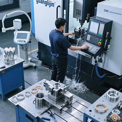
Aerospace machining is a game of margins. Tolerances shrink, documentation grows, and a drifting axis can scrap a part worth more than the controller itself. The 3 axis CNC controller sits at the center of that risk. It decides how faithfully a tool path becomes metal. This guide explores what an advanced controller must deliver for aerospace work, how to compare options, and where integration efforts typically fail.
What Makes an Aerospace Control Solution Different
Aerospace parts carry varied tolerance bands. Structural brackets may run ±0.05 to ±0.10 mm. Actuator housings often require ±0.01 to ±0.025 mm. Flight-critical components push toward ±0.002 to ±0.005 mm .
Each band places different demands on the control loop. A controller must interpret dense G-code without stalling. It must issue smooth velocity commands to servo drives. It must react to feedback signals in real time.
Generic controllers built for routing wood will not hold these bands across long cycles. Aerospace work rewards stability, not peak speed. The controller must remain predictable from the first cut of the shift to the last.
The Core Functions of a 3 Axis CNC Controller
The controller is more than an operator screen. It plans motion, coordinates drives, and manages machine logic. It converts tool paths into discrete position commands and continuous velocity commands for each feed drive .
For aerospace work, an advanced 3 axis CNC controller should support:
- High-resolution interpolation for smooth surface finish
- Real-time error and thermal compensation inputs
- Encoder feedback compatibility across absolute and incremental formats
- Enough I/O for tool changers, probes, and safety interlocks
Before comparing brands, build a complete inventory of drives, motors, spindle interfaces, and feedback devices. A 3 axis CNC controller may match the axis count while missing the spindle or safety interface your machine needs .
Project A vs Project B: Two Aerospace Control Paths
Aerospace shops face two common scenarios. Project A is a supported replacement: the machine is mechanically sound, the drives are documented, and the goal is to restore original function. Project B is a full retrofit: the controls are obsolete, documentation is gone, and the shop wants modern capability.
| Decision Factor | Project A: Supported Replacement | Project B: Full Retrofit |
|---|---|---|
| Starting evidence | Known compatible configuration | Complete component inventory |
| Primary work | Restore and validate settings | Engineer and commission the system |
| Integration risk | Low to moderate | Moderate to high |
| Acceptance criterion | Original required functions work | All specified functions are proven |
| Typical timeline | Days to two weeks | Weeks to two months |
Neither path suits every shop. Replacement protects existing investment when the platform is stable. A retrofit makes sense when the frame is good but the electronics are a maintenance liability.
A Six-Step Selection and Commissioning Guide
- Inventory every retained component. Record drive models, motor specs, spindle interface type, encoder format, and auxiliary sensors. Never trust wire colors or memory alone.
- List all required machine functions. Homing sequences, limit switches, tool change logic, probing routines, coolant control, and safety circuits. Axis motion alone is not enough.
- Request written compatibility approval. Ask the supplier to confirm your full component list in writing. A matching connector does not prove electrical compatibility .
- Define who commissions the system. Identify the installer, the configurator, and the person who signs off on functional tests. Budget integration time, not just hardware.
- Test safety behavior first. Prove emergency stop, safe torque off, and limit switch response before any cutting demonstration. Safety failures are non-negotiable.
- Machine a representative aerospace part. Exercise the tightest tolerance band, surface finish requirement, and cycle time target. Accept the system only after that part passes inspection.
Thermal Drift and Why Compensation Matters
Spindle bearings heat up. Ball screws expand. Ambient shop temperature shifts by a few degrees. A one-meter steel machine bed expands more than 55 micrometers under a five-degree change .
For aerospace work requiring ±0.005 mm, a two-degree thermal shift can breach the specification. The controller cannot stop physics. It can compensate for the consequences.
Advanced controllers accept external temperature sensors or run internal compensation algorithms. The controller adjusts coordinate offsets in real time. Without this, operators stop production, measure parts, and update offsets manually. That process typically costs 15% to 20% of overall equipment effectiveness .
Our team ran a 2025 retrofit on a three-axis aerospace mill with documented thermal drift. After enabling sensor-based compensation, morning and afternoon part measurements converged within 0.008 mm. The machine did not change. The control strategy did.
Common Mistakes in Controller Selection
“More axes mean more capability.” A four-axis controller running a three-axis machine adds no precision. The idle channel just adds cost and configuration surface. Match the controller to the machine you own.
“Open-source is always cheaper.” The board may cost less. Integration engineering, missing documentation, and absent safety features often erase the savings. Aerospace work needs documented safety behavior.
“The controller determines accuracy.” The controller executes commands. Mechanical stiffness, drive tuning, thermal stability, and tool condition set the final result. A premium controller on a worn machine delivers worn results.
Frequently Asked Questions
Can a 3 axis CNC controller machine aerospace aluminum brackets?
Yes, for structural brackets and non-flight-critical parts where ±0.05 to ±0.10 mm is acceptable . Tighter work requires thermal compensation and precise encoder feedback.
What is the difference between a 3 axis controller and a motion control board?
A motion board outputs step and direction signals. A complete 3 axis CNC controller includes motion planning, I/O management, spindle control, and the operator interface. The scope is broader.
How much does an aerospace retrofit 3 axis CNC controller cost?
Hardware ranges from a few thousand dollars for basic boards to over fifteen thousand for industrial systems with enclosure and drives. Total cost includes integration, commissioning, and downtime.
Do I need closed-loop feedback for aerospace fabrication?
Closed-loop feedback verifies position and detects errors. For flight-critical work, closed-loop control combined with thermal monitoring provides the stability drawings demand .
What should I verify before buying a used 3 axis CNC controller?
Check firmware version, available I/O, encoder compatibility, and manufacturer support. A used controller without documentation or software updates becomes a maintenance burden.
Pre-Purchase Checklist
Before You Commit to a Controller
- Record all existing drive, motor, and encoder model numbers.
- List every machine function beyond axis motion: spindle, tool change, probe, coolant, safety.
- Confirm the controller’s encoder protocol matches your feedback devices.
- Obtain written compatibility approval for the full component list.
- Assign installation and integration responsibility in writing.
- Verify emergency stop, safe torque off, and limit switch behavior.
- Plan a representative test part at your tightest tolerance.
- Confirm thermal compensation support for ±0.01 mm work or tighter.
- Request configuration backups and final documentation as deliverables.
- Set written acceptance criteria before placing the order.
Aerospace fabrication rewards preparation and punishes assumptions. The right 3 axis CNC controller is not the cheapest or the most feature-heavy. It is the one that integrates cleanly, holds your tolerance band, and can be maintained without guesswork. Start with the inventory. Prove the interfaces. Test the part. The rest follows.