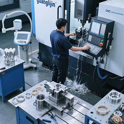
Profiling aerospace parts is a balance between removing material fast and holding wall geometry true. A trusted 2.5 axis CNC machine handles the flat-and-stepped profiling that fills most aerospace work orders. It keeps cycles short and programming predictable. But trust is earned through repeatable results, not brand claims.
This article examines profiling strategy, machine trust factors, and the integration steps that separate a smooth aerospace run from a costly one.
Profiling Aerospace Parts With Level-Based Cutting
Profiling means cutting the outer boundary and internal cutouts of a part. Aerospace profiles often include flanges, ribs, and stepped edges. Many of these sit at constant depth or change depth in discrete steps.
Level-based profiling cuts each depth plane in sequence. The cutter follows the outline, drops to the next level, and repeats. This produces clean walls and predictable chip loads .
Trusted profiling depends on consistent Z references. Spindle growth and fixture settling shift those references over a shift. A controller with thermal monitoring keeps the profile true without operator intervention.
The 2.5 axis CNC machine approach suits these profiles well. It removes the need for full surface interpolation while still producing aerospace-grade edges.
Project A vs Project B: Profile-Heavy or Surface-Heavy Work
Two aerospace jobs illustrate the difference. Project A is an airframe rib with constant-depth webs and stepped flanges. Project B is a curved fairing with a continuous exterior contour.
| Decision Factor | Project A: Airframe Rib | Project B: Curved Fairing |
|---|---|---|
| Profile type | Stepped, constant-depth edges | Continuous curved contour |
| Cutting method | Level-based profiling | Surface path interpolation |
| Inspection focus | Wall thickness and step height | Contour form and finish |
| Handwork risk | Low if tool radius matches corners | Higher if scallops remain |
| Machine fit | 2.5 axis profiling on 3-axis mill | 3-axis continuous path required |
Project A runs faster with level profiling. Project B needs continuous surface tracking. A trusted shop knows which method applies and does not force one onto the other.
A Six-Step Profiling Setup Guide
- Map every profile depth. Identify each constant-depth segment and every step transition. Mark the stock top and all finished edges.
- Check tool fit against corner radii. Confirm cutter diameter against internal corners and narrow slots. A tool that does not fit cannot cut the profile cleanly.
- Define the profiling sequence. Decide whether to cut outer boundary first or internal cutouts first. Sequence affects part rigidity during cutting.
- Verify fixture and clamp clearance. Profile cuts reach the part edge. Confirm clamps sit outside the tool path at every depth level.
- Set Z references and thermal baseline. Record initial Z position after spindle warm-up. Schedule a mid-shift reference check for long runs.
- Cut a representative profile and inspect. Measure wall thickness, step height, and edge finish. Accept the program only after inspection confirms the drawing.
Trust Factors in Aerospace Machine Selection
Trust is built from documented evidence. A controller rated for industrial duty. Drives with known compatibility. Spare parts available quickly. Firmware that fixes issues without replacing hardware.
Research on aerospace machining control shows that accurate discrete position and velocity commands from the controller are essential for reliable feed-drive performance . A trusted 2.5 axis controller delivers those commands consistently across thousands of cycles.
Trust also comes from thermal compensation. A one-meter steel bed expands more than 55 micrometers under a five-degree shift . In profiling work, that expansion changes wall thickness. A controller with compensation inputs corrects for it.
Our team reviewed a 2025 aerospace rib profiling run. Morning walls measured 0.012 mm thicker than afternoon walls. The program was identical. The shop added a warm-up cycle and a mid-shift offset check. Wall variation dropped below 0.006 mm.
Why Profile Rigidity Matters
Profiling removes material from the part edge. As the profile deepens, the remaining wall loses support. Thin aerospace walls deflect under cutting force. The finished part springs back after the clamp releases.
Therefore, profiling sequence matters. Cut internal cutouts before the outer boundary when possible. Leave support ribs until the final pass. Reduce radial engagement on thin walls.
A trusted profiling solution accounts for part rigidity. It is not only a tool-path question. It is a fixturing and sequencing question. The machine follows the plan, but the plan must respect the physics.
Common Mistakes in Aerospace Profiling
“Profiling is just cutting the outline.” Profiling includes internal cutouts, step transitions, and wall finishing. Treating it as a single outline pass misses critical geometry.
“Any tool that fits the slot will work.” Tool length, flute count, and coating affect wall finish and chatter. A tool that fits may still produce unacceptable surface marks on thin walls.
“Thermal drift is a three-axis problem only.” Drift affects Z depth and wall thickness in profiling too. Mid-shift checks apply to level cutting as well.
“Faster feeds are always better.” Aerospace alloys and thin walls limit feed rate. A slightly slower pass that holds tolerance beats a fast pass that scraps the part.
Frequently Asked Questions
Can a 2.5 axis CNC machine profile aerospace airframe ribs?
Yes, for ribs with constant-depth webs and stepped flanges. Curved contours require surface path interpolation even on the same machine .
What is the difference between 2.5 axis profiling and 3 axis contouring?
2.5 axis profiling cuts selected depth levels. 3 axis contouring follows continuously changing surfaces. Geometry decides which method applies .
How do I prevent wall deflection when profiling thin aerospace parts?
Sequence internal cutouts first. Leave support ribs until the final pass. Reduce radial engagement and verify clamp pressure does not distort the wall.
What should I check before trusting a 2.5 axis CNC machine for aerospace profiling?
Verify thermal compensation support, drive compatibility documentation, spare part lead times, and proven wall-thickness repeatability on a representative part.
How does thermal drift affect aerospace profiling accuracy?
Drift changes Z depth and wall thickness over a shift. A one-meter steel bed expands more than 55 micrometers under a five-degree shift . Mid-shift offset checks correct for it.
Profiling Readiness Checklist
Before the Profiling Run
- Map every profile depth and step transition.
- Confirm cutter diameter against all internal corner radii.
- Set the profiling sequence: internal cutouts before outer boundary.
- Verify clamp positions outside the tool path at every level.
- Run spindle warm-up and record initial Z reference.
- Confirm thermal compensation is enabled if available.
- Schedule a mid-shift reference and wall-thickness check.
- Check clamp pressure against thin-wall deflection risk.
- Cut a representative profile and measure wall thickness.
- Set written acceptance criteria before production begins.
Aerospace profiling rewards planning. The right 2.5 axis CNC machine solution matches level cutting to level geometry. It keeps Z references stable and respects wall rigidity. Trust comes from repeatable measurements, not from labels. Map the depths, check the tools, sequence the cuts, and verify the walls. The profile holds when the plan is sound.