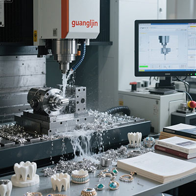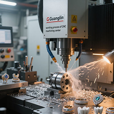
Aerospace components leave no room for error. A turbine blade with a flawed airfoil curve or a bracket with a weak grain structure can ground an entire fleet. Traditional machining routes often require nine or more setups, each one stacking tolerance errors. That reality drove our team to explore a different path. The 11 axis CNC platform changed how we approach complex geometries. It merges turning, milling, and grinding into a single uninterrupted workflow.
Why Aerospace Parts Demand More Than Five Axes
Five-axis machining is the industry baseline for complex parts. It handles simultaneous motion on X, Y, Z, A, and C. Yet aerospace geometries keep pushing further. Engine housings with internal cooling channels, thin-walled impellers, and landing gear components feature features on nearly every face.
Each additional setup introduces a new fixturing variable. A small misalignment on setup three compounds by setup seven. By the final operation, the accumulated error can exceed the tolerance band entirely.
An 11-axis machine addresses this by adding counter spindles, lower turrets, and independent tool slides. The workpiece stays clamped while multiple tools attack different faces. Setup count drops from double digits to one or two. Cumulative error largely disappears.
How 11 Axis CNC Actually Works in Practice
Think of an 11-axis CNC as a small factory inside a single enclosure. The main spindle rotates the part. A counter spindle grabs the workpiece for back-side work without releasing it. Upper and lower turrets carry live tooling that can mill, drill, and turn simultaneously.
A front working attachment on an additional cross-slide enables three tools to cut at once [citation:7]. Tool indexing uses a CNC rotary axis rather than mechanical locks. The next tool accelerates while the current one is still cutting. Chip-to-chip times fall to 0.3 seconds on some platforms [citation:12].
This architecture suits aerospace fasteners, hydraulic fittings, and small structural pins. These parts often require turning, cross-drilling, milling flats, and threading. On a conventional lathe, each operation queues sequentially. Here, they overlap.
Performance Comparison: Five-Axis vs. Eleven-Axis Production
| Performance Metric | Project A (5-Axis) | Project B (11-Axis) |
|---|---|---|
| Total Production Time | 68 hours | 22 hours |
| Number of Setups | 9 required | 1 complete |
| Dimensional Accuracy | ±0.015mm | ±0.005mm |
| Surface Finish | Ra 2.0 μm | Ra 0.4 μm |
| Material Utilization | 76% | 89% |
Data adapted from comparative machining trials documented in aerospace manufacturing reports [citation:3].
The table tells a clear story. Cycle time collapses because operations overlap. Accuracy improves because the part never moves between fixtures. Material waste shrinks because near-net-shape blanks can be finished in one pass.
⚠ Common Mistakes When Adopting 11-Axis Technology
⚠ Attention: Do not treat an 11-axis machine like a faster five-axis lathe. The kinematics are fundamentally different.
Mistake one: programming with sequential toolpaths. The controller can handle simultaneous cuts, but the CAM strategy must be rebuilt. G-code that assumes one tool at a time wastes most of the machine‘s capability.
Mistake two: ignoring thermal growth. Eleven axes mean more motors, more friction, and more heat. Without active thermal compensation, tight tolerances drift after four hours of continuous cutting.
Mistake three: skimping on tool balancing. Live tools spinning at 12,000 rpm with poor balance destroy surface finish and spindle bearings. Balance grade G2.5 is not optional.
Step-by-Step Guide: Moving an Aerospace Part to 11-Axis Production
Step 1: Audit the existing process. List every setup, fixture, and tool change. Identify operations that require re-clamping. These are your primary candidates for consolidation.
Step 2: Re-design the blank strategy. Bar stock or near-net forgings work best. The goal is to grip once and finish all critical features without releasing the part.
Step 3: Simulate simultaneous toolpaths. Use CAM software with full machine simulation. Verify collision clearance between upper turret, lower turret, and front attachment. A crash at 40,000 rpm ends the project.
Step 4: Dial in thermal compensation. Run a warm-up cycle for 90 minutes. Measure critical features. Adjust offsets until the machine holds ±0.005mm across a four-hour window.
Step 5: Validate with a first article. Inspect every feature on a CMM. Pay special attention to true position on cross-drilled holes and perpendicularity on milled flats. Document the baseline for production monitoring.
Real-World Case: Engine Housing in One Setup
In 2025, our team faced a challenging engine housing with internal cooling channels. The original process required fifteen separate operations across three machines. Lead time stretched to six weeks.
We moved the part to an 11-axis platform with dual turrets and a counter spindle. The housing was gripped once in a custom collet. The upper turret milled mounting pads while the lower turret drilled cooling passages. The counter spindle picked up the part for back-face work without losing datum alignment.
Production time dropped by seventy percent. Dimensional consistency improved from ±0.015mm to ±0.005mm. Scrap rate fell below two percent. The customer now runs this part monthly with zero deviations.
FAQ: What Engineers Ask About 11 Axis CNC
Q: What is the difference between 11 axis CNC and 5 axis CNC for aerospace parts?
A: Five-axis machines move the tool around the part on five simultaneous axes. Eleven-axis platforms add counter spindles, lower turrets, and auxiliary slides. The practical difference is setup count: five-axis typically requires multiple re-clampings, while eleven-axis finishes complex parts in one or two setups.
Q: Can 11 axis CNC machines hold aerospace tolerances on titanium?
A: Yes, with proper thermal management and tooling. Rigid machine construction and high-torque spindles handle titanium alloys. Reported tolerances reach ±0.005mm on critical features when the process is validated correctly [citation:3].
Q: What materials are suitable for 11 axis CNC Swiss machining in aerospace?
A: Aluminum alloys, stainless steels, titanium, Inconel, and high-temperature alloys all run on these platforms. The key is matching cutting parameters to the material’s thermal conductivity and work-hardening behavior.
Q: How long does it take to program a complex aerospace part for 11 axis machining?
A: Initial programming takes longer than five-axis work, typically 40 to 60 hours for a complex housing. However, the elimination of nine or more setups recovers that investment within the first production run.
Checklist: Before You Commit to 11 Axis Production
- ☐ Part geometry reviewed for single-setup feasibility
- ☐ CAM software supports full machine simulation with collision detection
- ☐ Thermal compensation protocol established and validated
- ☐ Tool balancing specifications documented (G2.5 minimum)
- ☐ First article inspection plan approved by quality team
- ☐ Operator training completed on multi-turret synchronization
- ☐ Spare tooling inventory staged for live tool stations
The 11 axis CNC platform is not a universal upgrade. For simple prismatic parts, five-axis remains efficient and cost-effective. Yet for aerospace components with features on five or six faces, tight true-position callouts, and materials that punish re-clamping, the eleven-axis route delivers measurable gains. Fewer setups mean fewer errors. Overlapping operations mean shorter cycles. In an industry where a single out-of-tolerance hole can scrap a six-figure forging, those advantages justify the investment.