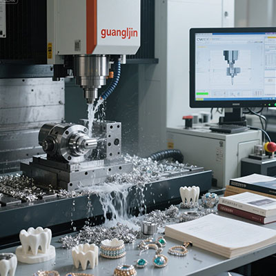
Feed rate is the most misunderstood setting on a router table. New operators pick a number from a forum. Then they wonder why the tool burns, the edge frays, or the spindle stalls. The answer usually sits in one number: chipload.
This guide explains how feed rate, spindle speed, and flute count work together on a 3 axis cnc router table. It covers a comparison of two cutting strategies, a five-step calculation routine, and a warning block. A closing checklist follows.
Why Chipload Beats Feed Rate Alone
Chipload is the thickness of material each cutting edge removes per revolution. It is the number that decides whether a cutter slices or rubs. Too small a chipload causes rubbing, heat, and tool wear. Too large a chipload overloads the spindle and breaks tools.
The formula is simple. Chipload equals feed rate divided by spindle RPM times the number of flutes. Rearranged, feed rate equals chipload times RPM times flutes. That single relationship governs every cut on a router table.
Material sets the target chipload. Softwood accepts a larger chip. Hardwood sits lower. Aluminum sits lower still. A 0.010-inch chipload in pine is healthy. The same figure in aluminum can snap a 3 mm cutter.
How RPM and Flute Count Interact
A two-flute cutter removes two chips per revolution. A four-flute cutter removes four. If you keep feed rate constant and double the flutes, chipload drops by half. That is why tool changes require feed rate recalculations, not just a new cutter in the collet.
Spindle RPM works the same way in reverse. Halve the RPM and chipload doubles at the same feed rate. Router tables often run high RPM for small tools. Therefore, feed rate must rise to keep chipload in the healthy range.
Project A vs Project B: Low Feed vs Calculated Feed on Aluminum
We compared two feed strategies on a router table cutting 6061 aluminum plate with a 6 mm two-flute end mill. One used a low feed rate from a forum post. The other used a calculated chipload. Our team tracked tool life and finish during a 2025 evaluation of router table cutting parameters.
| Parameter | Project A: Low Feed (Forum Setting) | Project B: Calculated Chipload |
|---|---|---|
| Spindle RPM | 12,000 | 12,000 |
| Feed rate | 400 mm/min | 1,200 mm/min |
| Chipload | ~0.008 mm (rubbing) | ~0.025 mm (cutting) |
| Tool life | ~40 minutes | ~3.5 hours |
| Edge finish | Burned, built-up edge | Clean, consistent |
| Spindle load | Low but unstable | Steady and controlled |
Project A looked cautious. It was actually the most abusive setting on the table. The tool rubbed instead of cutting, which generated heat and destroyed the edge. Project B raised the feed rate and cut cleaner for longer. Consequently, a low feed rate is not a safe feed rate.
How to Set Feed Rate on a Router Table: 5 Steps
Feed rate setting follows a calculation, not a guess. Work through this routine for each new tool and material combination.
Step 1: Find the Target Chipload for Your Material
Use the tool maker’s recommended chipload chart. Softwood runs higher. Hardwood sits mid-range. Aluminum and plastics sit lower. The chart gives a starting range, not a single number. Pick the low end for small tools and the high end for larger ones.
Step 2: Confirm Spindle RPM Range
Check the spindle’s rated RPM and the tool’s maximum RPM. Small-diameter tools tolerate high RPM. Larger tools and aluminum work need lower RPM to avoid heat. Set the RPM before calculating feed rate.
Step 3: Calculate Feed Rate From Chipload
Multiply chipload by RPM by flute count. A 0.025 mm chipload at 12,000 RPM with two flutes gives 600 mm/min. That number is your starting feed rate. Adjust from there based on sound and chip appearance.
Step 4: Watch the Chips and Listen to the Cut
Healthy chips look like small, consistent shavings. Dust means chipload is too low. Thick, rough chips mean chipload is too high. Listen for a steady cutting sound. A high-pitched scream signals rubbing or an overloaded tool.
Step 5: Adjust Depth of Cut Before Raising Feed
If the cut struggles, reduce depth of cut first. Feed rate and depth of cut both load the tool, but depth has a sharper effect. A lighter pass at the calculated feed rate cuts better than a heavy pass at half the feed.
- Running too slow to “be safe.” Low feed rates cause rubbing, heat, and built-up edge. The tool wears faster, not slower. Chipload must stay in the cutting range.
- Ignoring flute count when changing tools. A four-flute cutter at the same feed rate as a two-flute cutter halves chipload. Recalculate after every tool change.
- Raising feed rate before checking spindle load. A router spindle with limited torque stalls under aggressive feeds. Watch the load meter and reduce feed or depth when it climbs.
Material Starting Points for Router Tables
Softwood accepts chiploads around 0.010 to 0.015 inches with larger tools. Hardwood sits around 0.005 to 0.010 inches. MDF and particleboard tolerate moderate chiploads but dull tools faster because of abrasive content.
Aluminum runs low, often 0.001 to 0.003 inches per tooth, with lower RPM and shallow depth of cut. Plastics sit in between and need sharp tools to avoid melting. These are starting points, not fixed rules. Every router table and tool combination behaves slightly differently.
Frequently Asked Questions About Router Table Feed Rates
What feed rate should I use on a 3 axis CNC router table for aluminum?
Start around 0.001 to 0.003 inches chipload per tooth. At 12,000 RPM with a two-flute cutter, that lands near 600 to 1,800 mm/min. Reduce depth of cut before reducing feed if the spindle loads up.
Why does my router bit burn the wood?
Burning usually means chipload is too low. The tool rubs instead of cutting, generating heat. Raise feed rate or reduce RPM to increase chipload. Also check for a dull cutter or a buildup of resin on the flutes.
How do I calculate chipload for a router table?
Chipload equals feed rate divided by RPM times flute count. Rearrange to find feed rate: chipload times RPM times flutes. Use the tool maker’s chipload chart for the target range on your material.
Does depth of cut affect feed rate on a router table?
Yes. Deeper cuts increase tool load, so feed rate may need to drop. Reduce depth of cut first when the cut struggles. A lighter pass at the calculated feed rate outperforms a heavy pass at reduced feed.
Final Checklist Before Running a Feed Rate Test
- ☐ Chipload target selected from the tool maker’s chart
- ☐ Spindle RPM set within tool and spindle limits
- ☐ Flute count confirmed before calculating feed
- ☐ Feed rate calculated from chipload times RPM times flutes
- ☐ Depth of cut set conservatively for the first pass
- ☐ Spindle load monitored during the cut
- ☐ Chip appearance checked: shavings, not dust
- ☐ Cut sound checked for steady cutting, not screaming
- ☐ Parameters recorded for future batches
Feed rate is not a preference. It is a calculated output of chipload, RPM, and flute count. The router table rewards operators who do the math and punishes those who guess. When the chips look right and the spindle load stays steady, the settings are working. When they do not, the numbers tell you where to look.