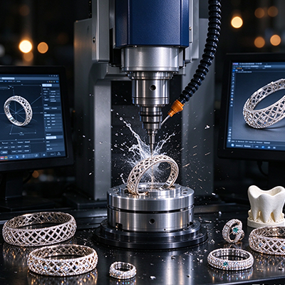
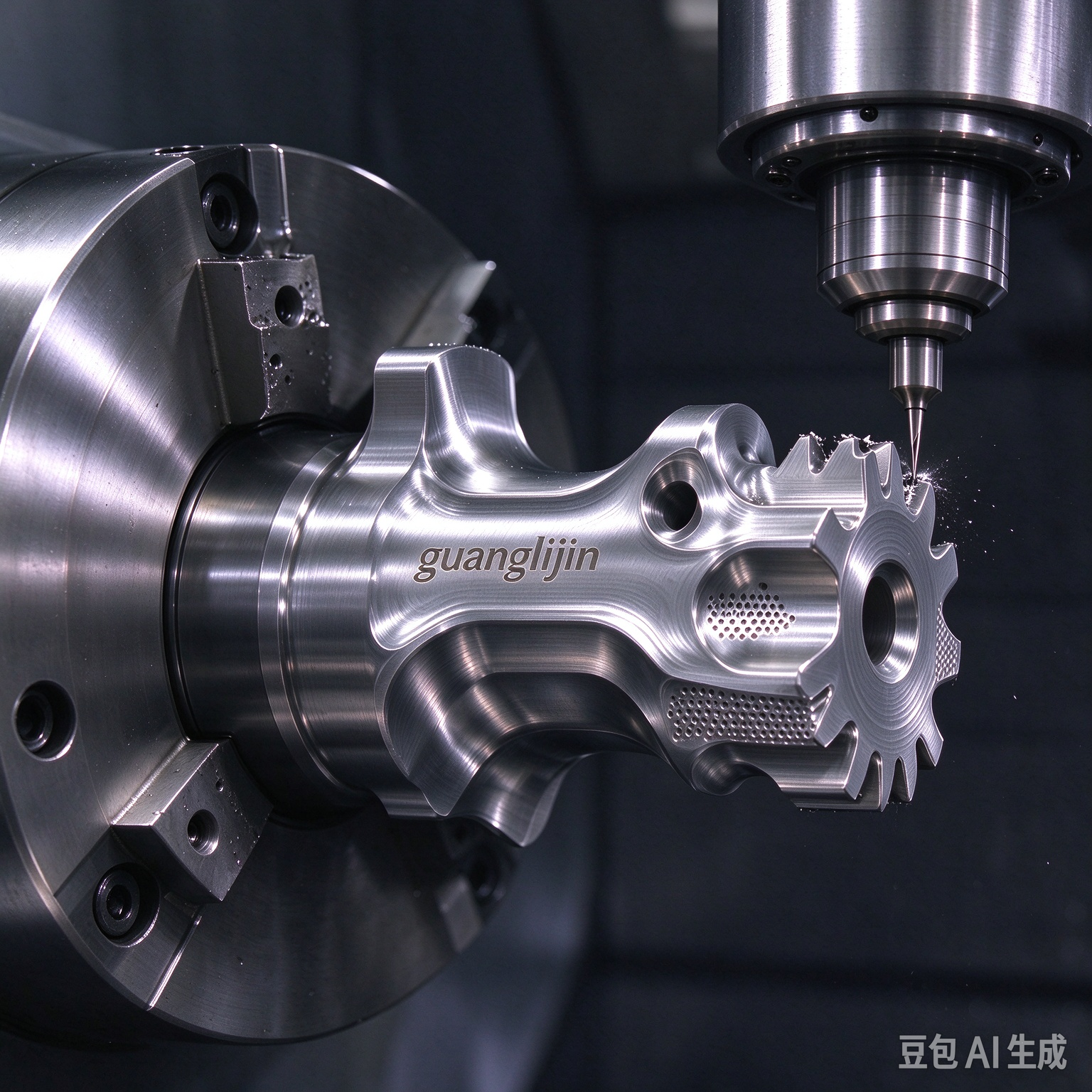
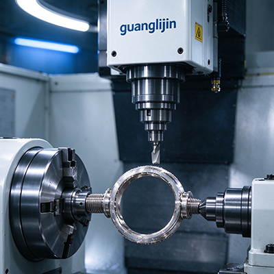
Aerospace parts demand tight tolerances and awkward geometry. Bracket lugs, duct segments, and sensor housings all fall into that family. A 5-axis desktop cnc platform can mill those parts well. However, the alloy list and the inspection discipline decide success. Not the axis count.
What Aerospace Milling Really Asks of a Compact Frame
Aerospace work asks three things. The machine must reach angled features in one setup. It must hold tolerance while cutting harder alloys. It must document results for traceability. Compact five-axis frames handle the first demand easily. The second and third demands take planning.
Aluminum aerospace parts suit compact mills well. Titanium and Inconel push the frame harder. Spindle torque and rigidity set the limit. Light finishing passes work. Heavy radial cuts do not.
Therefore, match part family to frame capability. Small aluminum housings and brackets run smoothly. Large titanium structural members belong on heavier equipment.
The Data Behind Compact Aerospace Work
Global shipments of desktop five-axis machine tools reached roughly 21,000 units in 2025. Average pricing sat near US$25,000 per unit. That growth pushed better controllers into the compact class. Tool-center-point management and probing are now common.
That matters for aerospace buyers. Single-setup machining removes reclamp error. Probing supports traceable datum verification. Compact five-axis milling can now meet aerospace documentation needs on small parts.
Aerospace suppliers also face audit pressure. Every setup needs a record. Every probe routine needs a saved definition. A compact mill supports that discipline when the operator builds the routine into the job traveler.
Project A vs Project B: Two Aerospace Milling Paths
Two shops can quote the same aerospace bracket. One delivers on time. The other reworks the batch. The gap usually sits in planning, not hardware.
| Factor | Project A — Aerospace-Ready Path | Project B — Unprepared Path |
|---|---|---|
| Material plan | Aluminum first, titanium in light finishing passes | Full-depth titanium roughing on a compact frame |
| Fixture design | Low-profile, full rotary clearance verified | Tall clamps, collision risk at tilt angles |
| Inspection | Independent CMM check plus saved probe logs | In-process probe only, no external verification |
| Traceability | Offsets and routines saved per part number | Manual zeroing, no records |
| Typical outcome | Audit-ready parts, stable yield | Drift, rework, and audit findings |
The difference is process. Aerospace buyers pay for evidence, not enthusiasm.
A Six-Step Guide to Aerospace Milling on a Desktop Mill
Aerospace work rewards fixed sequence. Each step removes a class of failure.
Step 1: Qualify the Alloy and Cut Parameters First
Run test cuts in the target alloy. Measure tool wear and surface finish. Titanium work-hardens fast. Confirm the spindle can hold torque through the pass. Log the winning parameters.
Step 2: Design Fixtures With Full Rotary Clearance
Simulate the full tilt range with the fixture model. A clamp that clears at zero degrees can strike at sixty. Low-profile vises and dovetail fixtures protect access.
Step 3: Lock the Warm-Up Cycle Into the Traveler
Aerospace tolerances leave little room for thermal drift. Warm the spindle and rotaries before tight cuts. Log the test-pass result. A cold frame cuts a different part.
Step 4: Probe and Document the Datum Scheme
Probe the stock and record the values. Save the routine per part number. Aerospace audits require evidence. A saved probe log is evidence.
Step 5: Cut a First Article and Verify With Independent Metrology
Measure critical features on a CMM or equivalent. In-process probing can share error with the cutter. External verification breaks that loop. Sign the traveler before release.
Step 6: Track Drift Across the Batch
Probe a known feature every few parts. Plot the values. Early drift signals thermal growth or tool wear. Correct before the batch drifts out of tolerance.
⚠ Attention: Three mistakes sink aerospace work on compact five-axis mills. First, roughing titanium at full depth. Compact frames lack the mass to absorb that load. Chatter and tool failure follow. Use light finishing passes and rough elsewhere. Second, relying on in-process probing as final inspection. The probe and cutter can share calibration error. Verify with independent metrology. Third, skipping probe logs on repeat parts. Aerospace audits require traceable evidence. Save routines and offsets per part number from day one.
Tooling and Strategy for Aerospace Alloys
Cutter choice drives success in harder alloys. Sharp geometry and positive rake reduce work hardening in titanium. High-feed inserts suit aluminum. Keep radial engagement modest on compact frames. Light passes protect the spindle and the finish.
Coolant strategy matters too. Through-tool coolant removes heat at the cutting edge. Flood cooling works on aluminum. Titanium benefits from high-pressure directed coolant. Compact mills may need an external pump to reach that pressure.
Climb milling improves finish on aerospace alloys. It also reduces work hardening. Keep tool overhang short. Long cutters flex and mark walls. Rigidity protects tolerance more than speed.
Our team supported a 2025 aerospace bracket run on a compact five-axis mill. The shop tried full simultaneous motion on every face. Cycle time climbed and finish suffered. Switching angled flats to indexed 3+2 cut cycle time by a third. Squareness held. The lesson is clear. Simultaneous motion earns its place on curves and undercuts. Flat angled faces do better with indexing.
Frequently Asked Questions
Can a 5-axis desktop CNC mill aerospace titanium parts?
Yes, in light finishing passes with sharp cutters and directed coolant. Compact frames lack mass for heavy titanium roughing. Qualify parameters with test cuts first. Keep radial engagement modest and monitor tool wear closely.
What aerospace parts suit a compact five-axis mill?
Small aluminum brackets, duct segments, sensor housings, and mounting plates fit well. Each carries angled features or curved surfaces inside a benchtop envelope. Large structural members do not fit the class.
How much does a 5-axis desktop CNC cost for aerospace shops in 2026?
The average global price sat near US$25,000 per unit in 2025, with roughly 21,000 desktop five-axis units shipped. Budget above that average for probing, coolant upgrades, and metrology access.
How do I meet aerospace traceability on a desktop five-axis mill?
Save probe routines and offset libraries per part number. Log warm-up test passes and drift checks. Verify first articles with independent metrology. Documented routines turn a compact mill into an audit-ready platform.
Is simultaneous five-axis motion needed for aerospace brackets?
Not always. Angled flats and holes work well with indexed 3+2 machining. Curved walls, undercuts, and impeller blades need simultaneous motion. Match the strategy to the geometry to protect cycle time.
Checklist: Aerospace Milling Readiness
- ☐ Target alloy qualified with logged cut parameters
- ☐ Fixture clearance verified through the full tilt range
- ☐ Warm-up cycle written into the job traveler
- ☐ Probe routine saved per part number
- ☐ Datum scheme documented for audit review
- ☐ First article verified with independent metrology
- ☐ Drift check scheduled across the batch
- ☐ Coolant pressure confirmed for the alloy
- ☐ Tool wear log started and reviewed
- ☐ 3+2 indexing used where simultaneous motion adds no value