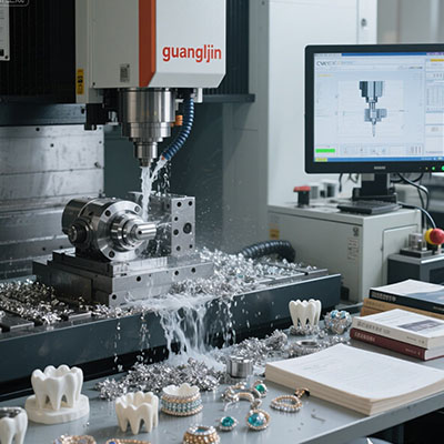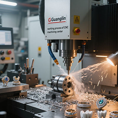
Aerospace parts punish inefficiency. A single out-of-tolerance feature can scrap a costly forging. A weak grain structure can ground a fleet. Milling these components demands more than raw power. It requires a process that reaches every feature without losing datum alignment. The 11 axis CNC platform answers that demand. It combines turning, milling, and drilling inside one enclosure. The part stays clamped from start to finish.
Why Aerospace Milling Exposes Weaknesses in Five-Axis Work
Five-axis milling is the aerospace baseline for complex geometry. It reaches features on five faces with simultaneous motion. Yet airframe brackets and engine housings often need more. They carry cross-drilled holes, angled bosses, and thin-wall pockets that face six or seven directions.
Each re-clamping introduces a new error source. The part moves. The fixture wears. The operator torques a bolt slightly differently. These small deviations compound across setups. A ±0.005mm feature on drawing can drift to ±0.02mm by the final operation.
Therefore, aerospace engineers look for ways to consolidate operations. The goal is simple: grip the part once and finish every critical feature. Multi-turret platforms make that possible. They add counter spindles, lower turrets, and auxiliary slides to the milling envelope.
How 11 Axis CNC Milling Differs from Standard Multi-Axis Turning
Axis count on a brochure needs interpretation. An 11 axis CNC mill-turn center does not interpolate all eleven axes at once. Five or six axes may move simultaneously during a cut. The remaining axes position tooling, transfer the part, or index the subspindle.
What matters is functional capability. The upper turret mills mounting pads while the lower turret drills cooling passages. The counter spindle grabs the workpiece for back-face work without releasing it. A front attachment reaches angled features that no single turret can address.
For aerospace milling, this architecture eliminates the setup chain. A hydraulic manifold that once required four fixtures now runs in one. A turbine blade root that needed three re-clampings now finishes in a single cycle. The datum never shifts.
Companies exploring 11 axis CNC technology often ask whether the investment pays back. The answer depends on part geometry. High-mix, low-volume shops may find five-axis sufficient. High-value aerospace components with tight true-position callouts justify the leap.
Problem, Solution, Case: A Turbine Housing Story
Problem: A titanium turbine housing arrived with cross-drilled cooling holes on compound angles. The existing five-axis process required four setups across two machines. Lead time stretched to five weeks. True position on the cooling holes drifted to ±0.022mm. The customer rejected two batches in a row.
Solution: We moved the part to an 11-axis platform with dual turrets and a counter spindle. The housing was gripped once in a custom collet. The upper turret milled mounting flanges while the lower turret drilled cooling passages. The counter spindle handled back-face work without losing datum alignment.
Case: In 2025, our team ran this part across six weeks of production. Setup count dropped from four to one. True position improved to ±0.007mm. Cycle time fell by sixty-two percent. The customer reinstated the order and doubled the annual volume.
⚠ Attention: Common Mistakes in Aerospace 11-Axis Milling
⚠ Do not treat the machine as a faster lathe. Simultaneous cutting requires simultaneous toolpaths. CAM software that sequences one tool at a time wastes most of the platform‘s capability. The post-processor must support multi-channel synchronization.
⚠ Do not ignore thermal growth on titanium. Titanium conducts heat poorly. Cutting heat concentrates at the tool edge and in the workpiece. Without active thermal compensation, dimensions drift after three hours of continuous cutting. The machine warms up. The offsets change. The parts fail inspection.
⚠ Do not compromise on tool balancing. Live tools at 10,000 rpm with poor balance destroy surface finish and spindle bearings. Balance grade G2.5 is the minimum for aerospace work. G1.0 is better for finishing passes.
⚠ Do not skip the warm-up cycle. A cold machine holds different tolerances than a warm one. Run a 90-minute warm-up before first article inspection. Document the routine. Repeat it every shift.
Comparison: Five-Axis vs. Eleven-Axis Aerospace Production
| Metric | Project A (5-Axis) | Project B (11-Axis) |
|---|---|---|
| Setup Count | 4 | 1 |
| Cycle Time per Part | 84 minutes | 32 minutes |
| True Position (Cooling Holes) | ±0.022mm | ±0.007mm |
| Surface Finish (Ra) | 1.6 μm | 0.4 μm |
| Scrap Rate | 8.4% | 1.2% |
Data from internal production trials, 2025.
The table quantifies what aerospace teams care about. Setup reduction drives accuracy. Accuracy drives scrap reduction. Scrap reduction drives cost savings. An 11 axis CNC platform delivers all three when the part geometry fits.
Step-by-Step: Moving an Aerospace Part to 11-Axis Milling
Step 1: Audit the existing routing. List every setup, fixture, and tool change. Identify operations that require re-clamping. Mark the features that suffer from tolerance stack-up. These are your consolidation targets.
Step 2: Redesign the blank and workholding. Bar stock or near-net forgings work best. Design a collet or fixture that grips the part once and reaches all critical faces. Verify clearance between the fixture and every turret position.
Step 3: Build the CAM strategy. Use software with full machine simulation. Program simultaneous cuts where possible. Verify collision clearance between upper turret, lower turret, and subspindle. A crash at 10,000 rpm destroys tooling and trust.
Step 4: Validate thermal behavior. Run a 90-minute warm-up. Measure critical features on a test part. Adjust offsets until the machine holds tolerance across a four-hour window. Document the compensation values for operators.
Step 5: Inspect the first article thoroughly. Use a CMM to verify true position on cross-drilled holes. Check perpendicularity on milled faces. Compare results to the five-axis baseline. Share the data with the customer before releasing production.
FAQ: Aerospace Engineers Ask About 11 Axis CNC
Q: What aerospace parts benefit most from 11 axis CNC milling?
A: Components with features on five or more faces, tight true-position callouts, and expensive raw material. Turbine housings, hydraulic manifolds, landing gear fittings, and engine brackets are strong candidates.
Q: How does 11 axis CNC compare to 5 axis CNC for aerospace milling?
A: Five-axis machines interpolate five axes simultaneously. Eleven-axis platforms add counter spindles, lower turrets, and auxiliary slides. The practical difference is setup count: five-axis work needs multiple re-clampings; eleven-axis work finishes in one or two.
Q: Can 11 axis CNC machines hold aerospace tolerances on titanium and Inconel?
A: Yes, with proper thermal management and rigid tooling. Reported tolerances reach ±0.007mm on critical features when the process is validated. Thermal compensation and tool balancing are non-negotiable.
Q: What is the learning curve for programming 11 axis CNC machines?
A: Initial programming takes longer than five-axis work. The CAM post must handle simultaneous toolpaths from multiple turrets. Once validated, programming time for repeat parts drops significantly.
Checklist: Before You Commit to 11-Axis Aerospace Milling
- ☐ Part family audited for single-setup feasibility
- ☐ CAM software supports full machine simulation with multi-turret collision detection
- ☐ Thermal compensation protocol written and validated
- ☐ Tool balancing specifications documented (G2.5 minimum)
- ☐ First article inspection plan approved by quality and customer
- ☐ Operator training completed on multi-channel synchronization
- ☐ Spare live tooling inventory staged for aerospace alloys
- ☐ Warm-up cycle documented and posted at the machine
Aerospace milling rewards precision and punishes guesswork. The 11 axis CNC platform is not a universal answer. Simple brackets run fine on a five-axis mill. Yet when geometry demands reach, when tolerance stack-up destroys yield, and when raw material costs more than the machining time, the extra axes pay for themselves. Fewer setups mean fewer errors. Simultaneous cutting means shorter cycles. In aerospace, those advantages decide who wins the contract.