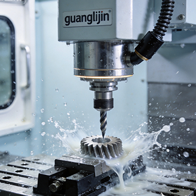
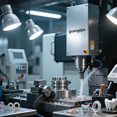
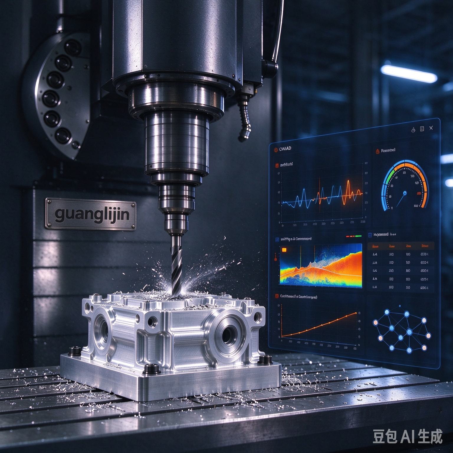
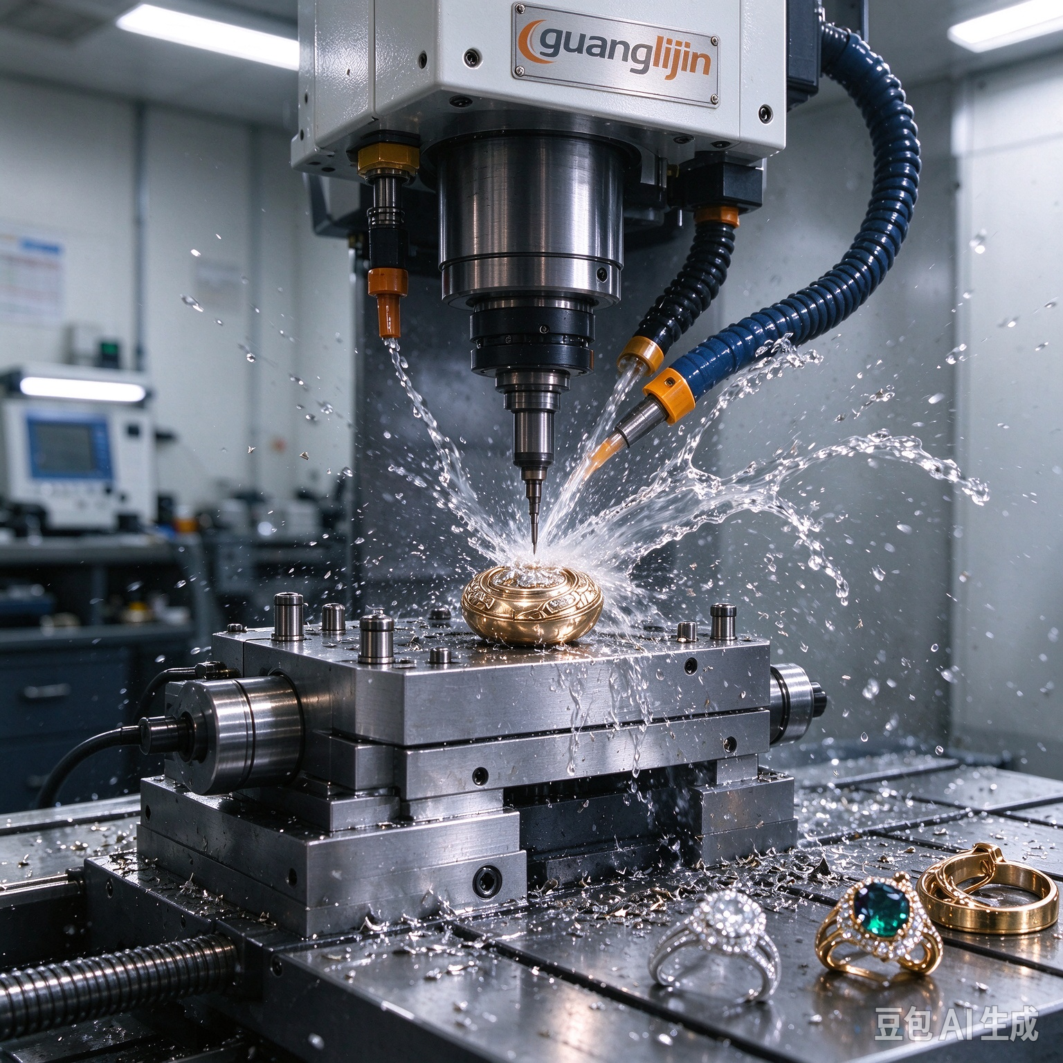
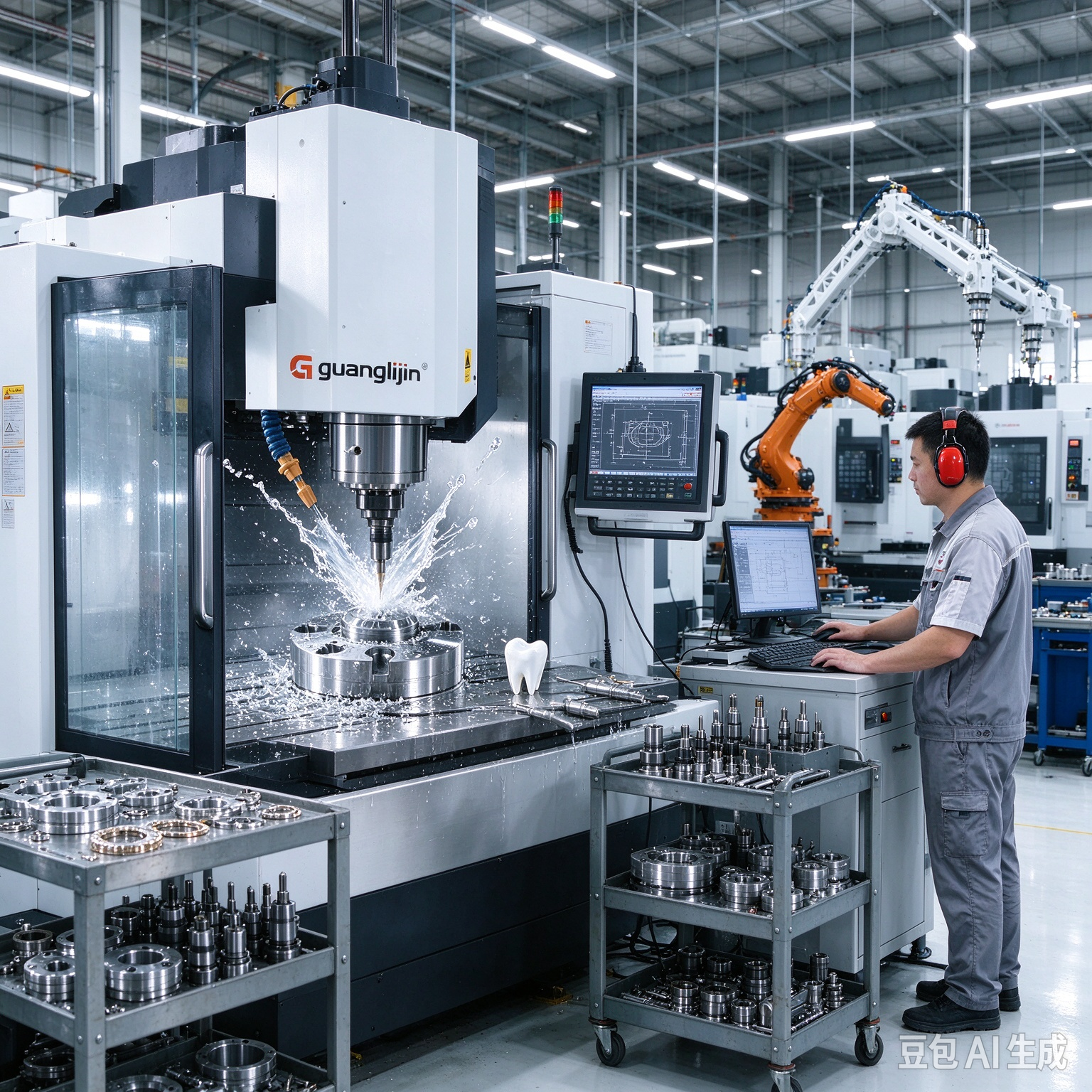
Why do complex parts still bounce between machines? The answer is reach. A five-axis mill reaches most surfaces, but not all. Undercuts, deep compound angles, and back-side features force extra setups. An 8 axis cnc platform changes that equation. The extra rotary and linear axes bring nearly every surface into reach without reclamping.
What the Extra Axes Actually Deliver
An eight-axis system adds motion beyond the standard five. Typical configurations include a second rotary table, a tilting spindle carrier, or a synchronized sub-spindle. The exact layout varies by builder. The outcome is consistent. The tool can approach the workpiece from directions a five-axis frame cannot.
This matters for parts with internal pockets behind flanges. It matters for cross-drilled ports on curved walls. It matters for any geometry that forces a five-axis shop to stop, unclamp, and re-fixture.
However, axis count alone proves nothing. The controller must interpolate all eight axes together. Tool-center-point management must hold the tip on path through every tilt. Without that coordination, the extra axes just add collision risk.
The Efficiency Case in Numbers
Aerospace data points to a real gap. A 2025 report from the Aerospace Manufacturing Institute found that eight-axis platforms reduce non-cutting time by up to 62% compared to five-axis cells [citation:6]. That figure covers setup, refixturing, and requalification between operations.
Cycle time tells a similar story. One documented case involving a titanium volute casing showed throughput improving by 47% after moving from four separate setups to a single eight-axis clamping [citation:6]. A separate fuel manifold case cut cycle time from 9.4 hours to 5.1 hours [citation:6].
Therefore, the efficiency gain is not marginal. It comes from eliminating the gaps between operations. Every reclamp carries datum error, prove-out time, and inspection risk. Eight-axis machining removes those gaps from the process.
Project A vs Project B: Setup Strategy Compared
Two shops can machine the same aerospace bracket. One uses five-axis plus secondary operations. The other uses a single eight-axis setup. The difference shows up in yield and cycle time.
| Metric | Project A — Five-Axis + Secondary Ops | Project B — Eight-Axis Single Setup |
|---|---|---|
| Total setups | 3 separate clampings | 1 clamping |
| Cycle time (titanium housing) | 18.6 hours | 11.2 hours |
| First-pass yield | 86% | 96.5% |
| Tool consumption per part | $142 | $97 |
| Inspection rework rate | 12% | 2.1% |
Those numbers come from a direct comparison of the two strategies [citation:6]. The pattern is clear. Single-setup machining removes error sources and cuts non-cutting time together.
A Six-Step Implementation Guide for Eight-Axis Work
Adopting eight-axis machining is a process change, not a machine swap. Follow a fixed sequence. Each step prevents a class of failure.
Step 1: Build a Full Kinematic Digital Twin
Model the machine, tool assemblies, and stock in simulation. Exercise extreme tilt angles. Check collision zones around the second rotary table. With eight axes, collision risk grows fast. Simulation catches it before the spindle does.
Step 2: Develop a Custom CAM Post-Processor
Standard five-axis posts do not handle eight-axis kinematics. Build a post that synchronizes rotary moves with linear interpolation. Use tool-axis smoothing on curved surfaces. Jerky rotary motion leaves marks that no finish pass can hide.
Step 3: Install Zero-Point Workholding With Full Access
Modular zero-point clamping gives repeatability within microns and clears the rotary travel. Tall vises block the extra axes. Low-profile systems protect access and repeatability together.
Step 4: Select Toolpaths That Use the Extra Reach
Trochoidal milling and barrel cutters benefit from eight-axis orientation. The tool can engage the workpiece at an optimal angle without repositioning stops. Adaptive toolpaths keep loads steady on superalloys.
Step 5: Probe Critical Datums After Roughing
Roughing moves material and heat. Probe key features before finishing. Compare against the model. Correct offsets before the finish pass. In-process probing turns a long cycle into a controlled one.
Step 6: Compensate Rotary Thermal Growth
Eight axes generate more heat than five. The second rotary table grows as it runs. Log drift on a known feature at fixed intervals. Apply compensation before tolerance erodes. Stability requires measurement, not assumption.
⚠ Attention: Three mistakes undermine eight-axis programs. First, treating the machine like a five-axis frame with extra moves. Without full kinematic simulation, crashes into the second rotary table become common. Second, skipping backlash checks on the added rotary axes. Position drift appears slowly, then ruins a batch. Third, using a five-axis post-processor without modification. The output may look correct in simulation but fail at the machine. Build the post for the actual kinematic chain.
Where Eight-Axis Machining Fits Best
Aerospace components dominate the use case. Structural ribs with compound-angle bosses, fuel manifolds with cross-drilled ports, and turbine shrouds with undercuts all benefit. Each carries features that force multiple setups on a five-axis frame.
Medical implants and complex mold inserts also fit. Any part with back-side features or intersecting angled surfaces gains from single-setup access.
Our team worked with a supplier in early 2025 that struggled with turbine shroud consistency. The shop ran five-axis plus a secondary angle-head operation. After moving to an eight-axis platform, scrap dropped from 7.2% to 1.8% within three months [citation:11]. The geometry had not changed. The number of times the part moved had.
However, eight-axis machining is not universal. Simple prismatic parts run faster on a three-axis mill. The extra axes add programming time and simulation cost. Match the platform to the part family, not to the axis count.
Frequently Asked Questions
What is the difference between 5-axis and 8 axis CNC machining?
Five-axis systems use three linear and two rotary axes. Eight-axis systems add extra rotary or linear motion, such as a second rotary table or tilting spindle carrier. This allows single-setup access to undercuts and back-side features that force multiple setups on a five-axis frame.
What parts benefit most from 8 axis CNC machining solutions?
Aerospace structural ribs, fuel manifolds, turbine shrouds, and medical implants benefit most. These parts carry compound angles, internal pockets, or undercuts that require refixturing on five-axis equipment. Single-setup machining removes datum shifts and cuts cycle time.
How much cycle time can 8 axis CNC save compared to 5-axis?
Documented cases show cycle time reductions of 39% to 47% on complex parts. Non-cutting time can drop by up to 62%. The gain comes from eliminating setups, not from faster cutting speeds. Fewer clampings mean less prove-out and inspection time.
What CAM software supports 8 axis CNC machining?
High-end CAM platforms like Siemens NX, CATIA, and hyperMILL support eight-axis kinematics. The critical piece is a custom post-processor built for the specific machine configuration. A standard five-axis post will not output correct code for the full kinematic chain.
Is 8 axis CNC harder to program than 5-axis?
Yes. The extra axes expand collision zones and require full kinematic simulation. Tool-axis smoothing and synchronized rotary interpolation add programming complexity. The investment pays back on parts that would otherwise need multiple setups.
Checklist: Eight-Axis Machining Readiness
- ☐ Full kinematic digital twin built and collision-tested
- ☐ Custom CAM post-processor verified on the controller
- ☐ Zero-point workholding installed with rotary clearance
- ☐ Toolpaths selected for the extra reach
- ☐ Probing routine scheduled after roughing
- ☐ Rotary thermal drift logged at fixed intervals
- ☐ Backlash check scheduled on all added axes
- ☐ First article verified with independent metrology
- ☐ Part family screened for eight-axis suitability
- ☐ Recovery playbook posted for rotary fault scenarios